Whole Building Surge Protection: IEC 61643-11 Selection & Installation Guide for Contractors and EPC Engineers
Quick Answer
Whole building surge protection under IEC 61643-11 requires a minimum of two coordinated protection stages:
- Type 1 or Type 1+2 SPD at the main distribution board (MDB) — handles incoming lightning current (10/350 μs, Iimp-rated). Required when the building has an external LPS or an overhead power supply.
- Type 2 SPD at every sub-distribution board (SDB) — intercepts internally generated switching surges (8/20 μs, In-rated) from VFDs, HVAC, elevators, and capacitor banks.
A single SPD at the service entrance alone does not comply with the IEC 62305-4 layered protection concept and leaves all internally generated surges unaddressed.
Electrical surges destroy equipment quietly. A switching event from a variable-frequency drive two floors up can degrade a PLC input card over months before anyone notices. This guide covers every engineering decision that separates a compliant, high-performance whole building surge protection design from one that looks correct on paper but fails in service.
1. Why Surge Protection Is a Design Requirement, Not an Add-On
For years, surge protective devices were treated as optional line items. That position is no longer defensible.
IEC standards require it. IEC 60364-5-53:2019, Section 534, covers the selection and erection of SPDs in buildings. For any building with an external lightning protection system (LPS) or an overhead power supply, the standard points to a Type 1 or Type 1+2 SPD at the service entrance. IEC 62305-4 builds an entire design methodology around this requirement.
The equipment being protected is more vulnerable than it used to be. A modern variable-frequency drive, building management system controller, or IP-based security panel typically cannot tolerate what older equipment shrugged off. An SPD with a voltage protection level (Up) of ≤ 1.5 kV ensures the transient voltage reaching that equipment stays within its insulation withstand rating.
The financial case is straightforward. A Type 1+2 DIN-rail SPD at the main distribution board represents a fraction of one percent of the protected equipment value. Specifying surge protection is one of the highest return-on-investment decisions on any IEC 61643-11 compliant electrical installation.
2. Where Surges Actually Come From in Commercial Buildings
The widespread belief that surges are primarily a lightning problem leads directly to chronic under-specification. Lightning-induced surges account for a minority of total surge events in a typical building.
The more frequent threat is internally generated:
Variable-frequency drives (VFDs) and motor starters. A facility with ten VFDs has ten active, continuous internal surge sources. Transients from VFD switching routinely reach 1–3 kV on 400 V systems.
HVAC systems. Compressor and fan motor contactors generate switching transients every start/stop cycle — potentially thousands of times per day.
Elevator and escalator drives. Regenerative drives feed energy back into the supply network during deceleration.
Power factor correction capacitor banks. Capacitor switching generates high-frequency transients that can momentarily reach several times the supply voltage.
UPS systems and standby generators. Transfer switching creates transient events at the moment of changeover.
None of these require a storm. They operate every day, in every building, regardless of weather conditions.
A surge protection strategy that installs one device at the service entrance and stops there misses the internally generated threats entirely — those transients never pass through the service entrance SPD.
This is why both IEC 60364-5-53 and IEC 62305-4 call for a layered protection approach across the whole building — one stage at the service entrance, additional stages at sub-distribution boards.
3. The IEC Lightning Protection Zone Framework
IEC 62305-3 and IEC 62305-4 introduce the Lightning Protection Zone (LPZ) concept as the systematic basis for whole building surge protection design. Understanding it transforms SPD placement from guesswork into a defensible engineering decision.
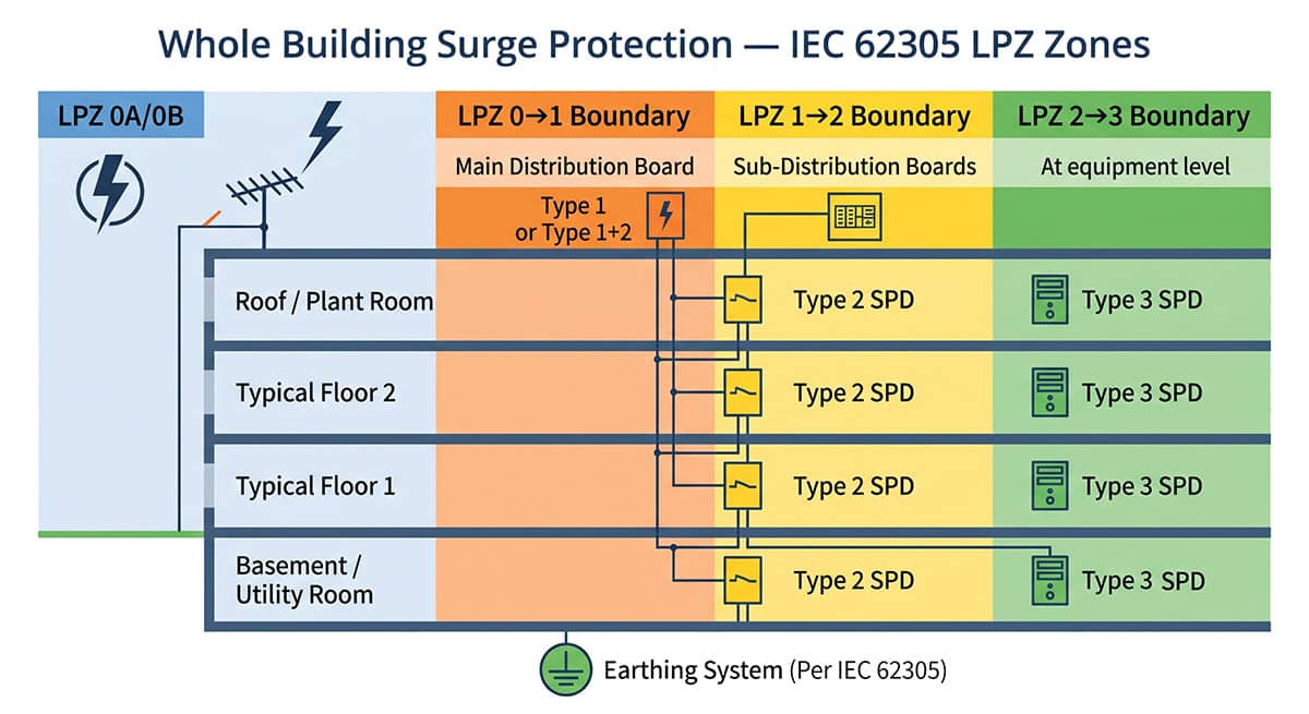
| Zone | Environment | Typical Location | SPD Type at Boundary |
|---|---|---|---|
| LPZ 0A | Direct lightning + full EM field | Rooftop, external cable routes | — |
| LPZ 0B | Shielded from direct strikes, full EM field | Under external LPS coverage | — |
| LPZ 0→1 | Building entry point | Main distribution board (MDB) | Type 1 or Type 1+2 |
| LPZ 1→2 | First interior zone | Sub-distribution boards (SDB) | Type 2 |
| LPZ 2→3 | Inner protected zone | Equipment level, control panels | Type 3 |
LPZ 0A is the unprotected external environment. LPZ 0B is shielded from direct strikes but still exposed to the full lightning electromagnetic field. LPZ 1 is the first interior zone — the Type 1 SPD belongs here, handling the highest-energy incoming surges (10/350 μs, Iimp). LPZ 2 is where the Type 2 SPD belongs (8/20 μs, In/Imax). LPZ 3 and beyond is where Type 3 SPDs provide fine protection closest to the load.
Key principle: No single SPD, regardless of its rating, provides adequate whole building protection on its own. The stages must be present at every zone boundary, matched to the boundary they defend.
4. Type 1 vs Type 2 vs Type 1+2: Which Goes Where
The three SPD types defined in IEC 61643-11 are not interchangeable. For a full technical comparison, see our Type 1 vs Type 2 vs Type 3 SPD comparison guide.
4.1 Type 1 SPD — Service Entrance / MDB
A Type 1 SPD is rated for the 10/350 μs lightning impulse current waveform. Its key rating parameter is Iimp. Type 1 devices are required when the building has an external LPS or when power arrives via overhead lines rather than underground cables.
A Type 2 SPD is not tested for the 10/350 μs waveform. If installed alone at the service entrance of a building with an external LPS, it will absorb energy far beyond its design rating during a direct lightning event — leading to immediate SPD failure, often without visible indication.
4.2 Type 2 SPD — Sub-Distribution Boards
A Type 2 SPD is rated for the 8/20 μs induced surge waveform, characterised by In and Imax. Type 2 devices belong at every sub-distribution board — internally generated surges never pass through the MDB SPD.
4.3 Type 1+2 Combined SPD — MDB Where Separation Is Not Achievable
A Type 1+2 combined device is certified to both the 10/350 μs and 8/20 μs test protocols. When separate Type 1 and Type 2 devices are installed in series, IEC 61643-12 requires at least 10 metres of cable between them. In most modern main panels this is physically impossible.
A Type 1+2 combined SPD resolves this by providing factory-coordinated dual protection in a single device — the standards-compliant solution for compact main panels and retrofits. See our Type 1+2 SPD selection guide.
| SPD Type | Test Waveform | Key Parameter | Installation Point | TrilPeak Series |
|---|---|---|---|---|
| Type 1 | 10/350 μs | Iimp (kA) | MDB / service entrance | TPK-I-50 |
| Type 1+2 | 10/350 + 8/20 μs | Iimp + In/Imax | MDB (when 10 m not achievable) | TPK-7, TPK-12.5 |
| Type 2 | 8/20 μs | In / Imax (kA) | Every sub-distribution board | TPK-20, TPK-40 |
| Type 3 | Combined | Uoc (V) | Equipment level | TPK-10 |
5. Critical Installation Rules That Determine Real-World Performance
Specifying the correct SPD type is necessary but not sufficient. See how to install a surge protector for the full step-by-step guide.
5.1 Lead Wire Length
Combined line-side and PE-side conductor length must not exceed 0.5 metres. With long leads, a device specified at Up = 1.5 kV can allow 3 kV or more to reach the load. Where straight runs exceed 0.5 m, use the V-connection method.
5.2 The 10-Metre Coordination Distance Rule
Separate Type 1 and Type 2 devices need a minimum of 10 metres of cable between them, or a coordination inductance (typically 1.5 μH). See our circuit breaker vs SPD coordination guide.
5.3 Backup Overcurrent Protection
Standard miniature circuit breakers (MCBs) may open under the impulse current of a Type 1 SPD installation. Always verify the backup device is rated for the application.
5.4 Earthing and Bonding
Surge protection can only perform to specification if the earthing system provides a low-impedance path for surge current discharge.
- The earth conductor from the SPD PE terminal to the main earthing busbar must be as short and direct as possible
- The main earthing busbar must be bonded to the building's equipotential bonding system
- All metallic services entering the building must be bonded at the point of entry
6. Earthing System Matters: TN-S, TN-C, and TT Configurations
The earthing system arrangement directly affects how an SPD must be configured. Specifying the correct SPD for the wrong earthing system is a compliance and safety error.
TN-S: the SPD must provide protection in L-PE, N-PE, and L-N modes. TN-C: the SPD connects between each line conductor and the PEN conductor; not permitted in new installations under IEC 60364. TN-C-S: installed on the TN-S side, downstream of the N/PE split point. TT: requires a 3+1 configuration — varistors between each line and neutral, plus a spark gap or varistor between neutral and PE, because the neutral can float above local earth potential.
Note: TrilPeak's TPK-7 and TPK-12.5 Type 1+2 series are specified for TN-S and TN-C systems. For TT installations, always verify the SPD model's rated protection modes before specification.
7. SPD Specification Checklist for Whole Building Surge Protection Projects
7.1 Step 1 — Establish the Threat Level
- External LPS present? → Type 1 or Type 1+2 required at MDB
- Overhead power supply? → Type 1 or Type 1+2 required at MDB
- Underground only, no external LPS? → Type 2 at MDB minimum
7.2 Step 2 — Map the LPZ Boundaries
- LPZ 0→1: main service entrance / MDB → Type 1+2 SPD
- LPZ 1→2: each sub-distribution board → Type 2 SPD
- LPZ 2→3: critical equipment rooms → Type 3 SPD
7.3 Step 3 — Check the Earthing System
- TN-S or TN-C-S: standard multi-mode SPD
- TN-C: SPD configured for PEN system
- TT: verify 3+1 neutral-PE protection coverage
7.4 Step 4 — Verify Uc Selection
- 230/400 V system: specify Uc ≥ 275 V
- Elevated TOV exposure: specify Uc ≥ 320 V or higher
- Always confirm Uc ≥ 1.1 × nominal supply voltage
7.5 Step 5 — Confirm Installation Constraints
- 10 m separation achievable? → If not, use Type 1+2 combined
- Lead wire ≤ 0.5 m total? → If not, plan V-connection routing
- Upstream overcurrent protection correctly rated for impulse current?
7.6 Step 6 — Document and Label
- Record SPD type, model, Iimp/In/Imax, Up, and installation date at each location
- Apply status indicator labels (green = functional, red = replace)
- Schedule inspection: annually or after significant lightning event; comprehensive every 2–4 years
- Know when to replace your SPD
8. Frequently Asked Questions
8.1 Do I need a Type 1 SPD if the building has no external lightning rod?
Not necessarily, but the absence of an external LPS is not the only trigger. If the power supply arrives via overhead lines rather than underground cables, a Type 1 or Type 1+2 is still the correct specification. Underground cables provide significant attenuation; overhead lines do not.
8.2 Can I install only one SPD at the main distribution board and skip the sub-boards?
No. Internally generated surges from VFDs, motors, and switching equipment inject transients directly onto sub-distribution circuits — these do not pass through the MDB SPD. Sub-distribution board protection is not optional if sensitive equipment is installed downstream, and this is the core principle behind whole building surge protection design.
8.3 What does Up ≤ 1.5 kV actually mean in practice?
Up is the voltage protection level — the maximum voltage at the SPD terminals during a standard test surge. IEC 60664-1 defines Category II equipment (most commercial and industrial loads) with a rated impulse withstand of 2.5 kV at 230 V. An SPD with Up ≤ 1.5 kV provides a comfortable margin, assuming correct installation with short lead wires.
8.4 Our client's equipment supplier says the equipment is already "surge protected." Does this replace the panel-level SPD?
No. Equipment-level protection is designed to handle residual low-energy transients after upstream stages have already clamped the bulk of surge energy — not the full energy of a distribution-level surge. Relying on equipment-level protection without panel-level SPDs is analogous to relying on a car's airbag without fitting seatbelts. See our surge protector vs UPS guide.
8.5 How often do SPDs need to be replaced?
MOV-based SPDs degrade with each surge event. Replace any SPD showing a red or fault indicator immediately. In high-lightning-exposure locations, plan for inspection after any significant storm event. See our full guide on when to replace a surge protector.
8.6 What is the difference between Type 1, Type 2, and Type 1+2 SPD?
Type 1 is rated for 10/350 μs lightning current (Iimp) and installs at the service entrance. Type 2 is rated for 8/20 μs induced surges (In/Imax) and installs at sub-distribution boards. A Type 1+2 combined device is certified to both waveforms — used when the 10-metre coordination distance cannot be achieved. See our Type 1 vs Type 2 vs Type 3 comparison guide.
Related Resources & Standards
Not sure which SPD configuration your project needs?
Use the TrilPeak SPD Selector to get a type and series recommendation in 60 seconds — or send us your single-line diagram and our engineering team will spec the full whole building surge protection installation for you. All TrilPeak SPDs are EN/IEC 61643-11 certified, DIN-rail mounted, and available with CE documentation for IEC-market projects worldwide.