
Grounding &
Earthing Accessories
The earth electrode system is the foundation every lightning protection system depends on. TrilPeak supplies copper-bonded earth rods, clamps, couplings, and bare copper conductors for IEC 62305-3 and EN 50164 compliant earthing. Send your project drawing or specification — we confirm material, dimensions and quantity and quote within 24 hours. Order alongside our ESE air terminals and Type 1 SPD as a complete system from one factory.

Grounding & Earthing Accessories — IEC 62305-3 Product Range
TrilPeak's grounding accessories range covers the complete IEC 62305-3 earth termination system. All items are available alongside TPKB ESE air terminals and Type 1 SPD so EPC contractors receive a single CE-documented lightning protection system from one supplier. Contact us for current specifications and project BOM pricing.
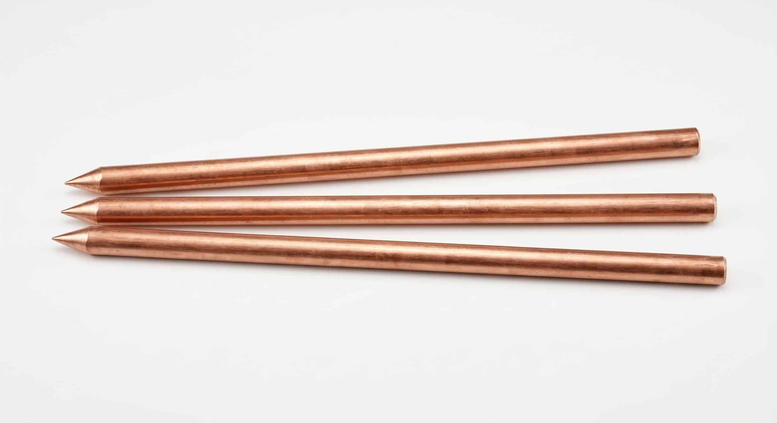
Copper-bonded steel earth rods are the most widely specified Type A electrode in IEC 62305-3 compliant installations. A steel core provides mechanical strength for driving into compacted or rocky ground; the electrolytic copper bond delivers long-term corrosion resistance and low contact resistance, meeting EN 50164-2 requirements for the design life of the installation.
Hardware for connecting down conductors to earth rod heads and joining extension rods for deep-drive assemblies. Material must be compatible with the conductor to prevent galvanic corrosion — stainless steel or brass is standard for copper-to-rod connections. Compliant with EN 50164-1 for long-term mechanical integrity and electrical continuity.
Bare copper flat tape for IEC 62305-3 down conductors and Type B ring earth electrodes. IEC 62305-3 specifies minimum cross-sections by protection level — 25mm² for Protection Level III/IV and 50mm² for Level I/II. Flat tape is preferred over round wire in most standards for its lower surface-area-to-volume ratio and easier mechanical fixing.
Equipotential bonding connects the LPS earth, power PE, and all metallic services entering the structure to a single common bonding bar — eliminating dangerous potential differences during a strike. This is also where the Type 1 SPD connects the power line to the LPS earth. IEC 62305-4 mandates bonding at every service entry point.
Grounding Accessories in the IEC 62305 Four-Zone System
Grounding accessories occupy Zone 0B — the earth termination that bridges the external LPS and the internal protected zones. TrilPeak supplies all four zones from one factory. See the full picture: what does a complete lightning protection system include?
Earthing System
One supplier for the complete chain. Ordering grounding accessories from the same factory as your ESE air terminal and SPD means one purchase order, one CE document set, one contact for the complete IEC 62305 BOM.
Earth Rod Selection — Type A & Type B for IEC 62305-3
Selecting the wrong electrode type or insufficient rod depth is the most common reason for failing the ≤10Ω target after installation. The table below summarises IEC 62305-3 requirements for both electrode types. For the full system context see our air terminal and LPS guide.
| Attribute | Type A Electrode | Type B Electrode |
|---|---|---|
| Definition | Vertical rod or horizontal conductor at base of each down conductor | Ring earth conductor encircling the structure, or foundation earth |
| Typical form | Copper-bonded steel rod, 1.5–3m, driven vertically | 25–50mm² bare copper tape buried at ≥0.5m depth |
| When to use | Standard structures in low–medium resistivity soil where ≤10Ω can be achieved | Large structures; Protection Level I/II; high-resistivity soil; when Type A alone fails ≤10Ω |
| IEC 62305-3 minimum | 1 electrode per down conductor. Min. length per Table 3 based on soil resistivity and protection level | ≥80% of conductor in soil contact. Ring radius ≥structure footprint |
| Resistance target | ≤10Ω — measured at each independent point, fall-of-potential method (IEC 62305-3 Annex E) | |
| Parallel rod spacing | ≥2× rod length between rods to minimise mutual interference | N/A — continuous ring conductor |
| Component standard | Rods: EN 50164-2 · Clamps: EN 50164-1 | Bare copper tape: EN 50164-1 · Clamps: EN 50164-1 |
Soil Type Determines Electrode Count and Depth
Soil resistivity (ρ, Ω·m) is the main variable affecting whether a single rod achieves ≤10Ω or whether a multi-rod array is needed. Always measure using the Wenner 4-electrode method before specifying electrode count and rod length.
| Soil Type | Typical ρ | Typical Approach |
|---|---|---|
| Moist clay / agricultural | 10–100 Ω·m | Single 2m rod typically achieves ≤5Ω |
| Loam / mixed urban | 100–300 Ω·m | 1–2 rods or deeper drive with extensions |
| Sandy / gravelly | 300–1000 Ω·m | Deep-drive extensions or Type B ring earth |
| Dry rock / granite | >1000 Ω·m | Horizontal buried conductors or ring earth; soil treatment may be needed |
Multiple Type A rods in parallel must be spaced ≥2× rod length. Two 2m rods need ≥4m separation — tighter spacing causes mutual interference that significantly reduces the expected resistance improvement.
Always test earth resistance before backfilling. If target is not met, add a second rod in parallel and re-measure before covering. Re-testing after burial is possible but far more disruptive.
Why Bonding LPS Earth to Electrical Earth Is Mandatory
IEC 62305-4 requires all metallic services entering a structure to connect to one common bonding bar. Without this, a 50kA strike through the LPS earth generates thousands of volts difference between LPS and power earth — enough to destroy any equipment bridging the two systems.
LPS down conductor earth · Power system PE · Gas pipe · Water pipe · Data cable screens · Structural steel. Every metallic service entering the building must terminate here at the point of entry.
The Type 1 SPD clamps live conductors to the bonding bar potential during a strike — this is how SPD and LPS work together. See: lightning arrester vs surge arrester.
IEC 62305-1 requires an LPS technical file recording the bonding scheme, measured earth resistance, and maintenance schedule. A lightning strike counter provides ongoing activation records for the maintenance file.
Grounding Accessories Installation — IEC 62305-3 Key Steps
The sequence below reflects IEC 62305-3 requirements for a Type A copper-bonded electrode installation. Full guidance is in our air terminal and LPS guide.
Soil Resistivity Survey
Measure ρ using Wenner 4-electrode method before specifying electrode design. Calculate rod count and length per IEC 62305-3 Annex C.
Route Down Conductors
Run copper tape from each air terminal via shortest direct path. No upward bends. Fix every 1–1.5m. Minimum 2 down conductors per structure at Level I/II with ≤20m perimeter spacing.
Drive Earth Rod
Drive copper-bonded rod with stainless driving cap. Add extension couplings as needed. Position ≥1m horizontally from building foundations.
Connect Conductor to Rod Head
Use stainless or brass clamp (EN 50164-1). Install accessible test link at base of down conductor above grade. Do not use zinc-coated fittings with copper.
Measure Resistance Before Backfilling
Fall-of-potential method per IEC 62305-3 Annex E. Target ≤10Ω. If not achieved, add second rod ≥4m away and re-measure.
Connect to Bonding Bar + Document
Connect LPS earth to main bonding bar. Verify all services terminate at same bar. Connect Type 1 SPD. Record the full bonding scheme and measured resistance values in the LPS technical file.

Complete LPS Supply — Including Grounding Accessories
TrilPeak's OEM programme covers ESE air terminals, grounding accessories, and surge protective devices under your brand label. Our ODM service supports custom material specifications. One factory, one CE document set. Volume pricing available for large orders.
Lightning Protection Earthing — Frequently Asked Questions
What earth resistance does IEC 62305-3 require?
IEC 62305-3 requires ≤10Ω at each electrode point, measured using the fall-of-potential method. Lower is better — ≤5Ω is preferred for critical structures. Re-measurement at scheduled intervals is required per IEC 62305-1 as part of the LPS maintenance plan.
What is the difference between Type A and Type B electrodes?
Type A are vertical rods or horizontal conductors at the base of each down conductor. Type B is a ring earth conductor buried ≥0.5m around the structure perimeter. Type B is required for Protection Level I/II, large structures, and where Type A alone cannot achieve ≤10Ω. Both types are detailed in IEC 62305-3 Clause 5.4.
Why are copper-bonded rods preferred over solid copper?
Copper-bonded steel combines the mechanical strength for driving into hard ground with copper's corrosion resistance. EN 50164-2 requires ≥250μm electrolytic copper bond for long-term performance. Solid copper deforms when driven and is significantly more expensive — verify bond thickness in any product specification.
Does the LPS earth need to connect to the electrical system earth?
Yes — IEC 62305-4 mandates this. All metallic services must share a common equipotential bonding bar. Without bonding, a strike current creates dangerous potential differences across any equipment bridging the two systems. The Type 1 SPD connects the power line to this bar.
How many earth rods are typically needed?
In low-resistivity soil (≤100Ω·m), a single 2m rod often achieves ≤5Ω. In medium-resistivity soil (100–300Ω·m), 2 rods spaced ≥4m apart are typical. For soil above 300Ω·m, deep-drive extensions or a Type B ring earth are needed. Always measure actual soil resistivity before specifying.
Can TrilPeak supply a complete IEC 62305 system BOM?
Yes. TrilPeak supplies ESE air terminals, grounding accessories, and the full SPD range from one factory. Send your project details and our engineers will prepare a complete BOM with CE documentation.
What are the NFPA 780 grounding requirements for lightning protection?
NFPA 780 requires a minimum electrode length based on soil resistivity — typically a single rod of at least 2.4m (8ft) for standard soil conditions. Each down conductor must have its own dedicated earth electrode. The system must achieve low impedance at the struck frequency. For full details refer to the NFPA official standards. TrilPeak supplies copper-bonded earth rods meeting both IEC 62305-3 and NFPA 780 grounding requirements.
Copper-Bonded Earth Rods — Ready to Ship
Standard copper-bonded earth rods in multiple diameters and lengths. IEC 62305-3 Type A electrode. EN 50164-2 compliant copper bond ≥250μm. Send your project specification for exact dimensions, quantities and pricing.
Request Grounding Accessories for Your LPS Project
TrilPeak supplies copper-bonded earth rods, clamps, couplings, and bare copper conductors alongside ESE air terminals and Type 1 SPD — complete IEC 62305 system from one CE-certified factory.