
Surge Protective Devices (SPDs): IEC 61643-11 Complete Guide
Quick Answers for Busy Engineers
Q: Which SPD type do I need for my facility?
A: Type 1+2 combined device at main board (high lightning risk/external LPS) + Type 2 at all sub-boards (standard). Type 3 optional for equipment >15m from Type 2.
Q: What's the difference between Type 1 and Type 1+2?
A: Type 1+2 is a single device certified for both Type 1 (Iimp 10/350µs) and Type 2 (In 8/20µs) tests. It combines both protection levels in one unit, eliminating coordination distance requirements and saving panel space compared to installing separate Type 1 and Type 2 devices.
Q: How do I choose the right SPD ratings?
A: Three critical values: Uc (275V for TN-S, 320V for TT), In (10kA industrial minimum), Up (≤2.0kV for sensitive equipment). See detailed selection guide below.
Q: What's the #1 installation mistake?
A: Leads >0.5m. Each meter adds ~1µH inductance = ~1kV voltage drop, negating protection.
Q: Is backup protection mandatory?
A: YES. IEC 61643-11 requires gG fuse (63-125A), MCB (C32-C63), or equivalent external overcurrent protection.
Q: How do I verify SPD quality?
A: Check the core component source. SPDs from manufacturers with vertical integration (in-house MOV production) offer superior consistency and response accuracy compared to brands that just assemble outsourced parts.
Q: What is the minimum grounding conductor (earthing conductor) size for SPDs per IEC 61643-11?
A: Type 1 SPD requires ≥16 mm² copper; Type 2 requires ≥10 mm²; Type 3 requires ≥4 mm². Maximum lead length: 0.5m for Type 1/2, 1.0m for Type 3. Using undersized grounding conductor (e.g. standard 2.5 mm² PE wire) is the most common IEC 61643-11 installation violation and significantly reduces surge protection effectiveness.
2025 Standard Update
IEC 61643-11:2025 (released June 2025) brings important changes:
- TT systems: Now need 350V SPDs (instead of 320V)
- Type 1+2: Stricter combined testing
- Large SPDs: Remote monitoring now required
See "What's New in 2025?" FAQ below for details.
Still have questions? Contact our engineering team.
Quick Summary
Terminology Note
This guide uses standardized terminology per IEC 61643-11:
Primary Terms:
- SPD (Surge Protective Device): IEC 61643-11 standard term for low-voltage power protection
- External Overcurrent Protection: IEC requirement (Clause 8.3.2.3) – generic term for backup devices
Common Implementations:
- gG Fuse (IEC 60269) – Universal standard solution, 63-125A typical rating
- MCB (IEC 60898) – Miniature Circuit Breaker, resettable option
Here's the essential SPD knowledge for low-voltage power systems:
- Surge protective devices are not optional: Even a single surge can destroy $20,000+ worth of VFDs, inverters, or PLCs—overvoltage suppression costs 0.5–2% of total electrical installation cost
- Three types, three layers: Primary stage at service entrance (lightning protection), secondary stage at distribution boards (workhorse for industrial), tertiary stage near sensitive equipment (final protection)
- Five critical parameters: Match Uc to your system voltage/grounding type, select In ≥ 10 kA for industrial applications, ensure Up < equipment withstand voltage, verify backup protection is installed
- Common mistakes kill protection: Long coiled leads (>0.5 m), wrong Uc for TT systems, missing backup fuses—all leave equipment vulnerable
- Reliability Beyond the Datasheet: Compliance isn't just about a certificate. Look for manufacturers that perform 100% routine testing rather than just batch sampling to ensure actual adherence to IEC 61643-11 standards.
Bottom line: If you design industrial LV systems, specify Type 1+2 at main boards and Type 2 at all sub-boards.
What Is a Surge Protective Device in Low-Voltage Power Systems?
Core principle: SPDs are parallel-connected devices that clamp voltage spikes and divert surge current to ground, protecting equipment from lightning, switching transients, and grid disturbances.
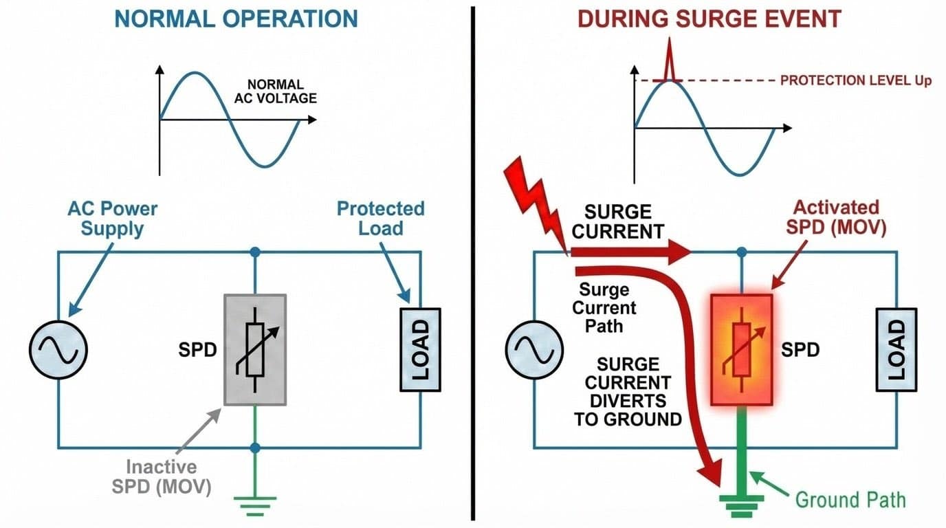
Figure 1: SPD operating principle – voltage clamping and surge current diversion during lightning strike
Key characteristics:
- Activates within microseconds when voltage exceeds safe threshold
- Clamps voltage to a protection level (Up) typically 1.0–2.5 kV
- Diverts surge current to ground while keeping circuit operational
- Does NOT interrupt power like circuit breakers—purely voltage limiting
Surge Protector vs. Other Protection Devices
Many engineers confuse surge protective devices with related protection technologies. Here's the critical distinction:
| Device | Primary Function | Protects Against |
|---|---|---|
| Surge Protective Device (SPD) | Limits transient overvoltages in LV systems (<1kV) | Lightning surges, switching transients |
| Circuit Breaker / Fuse | Interrupts overcurrent faults | Short circuits, overloads |
| Lightning Arrester (Air Termination) | Intercepts direct lightning strikes | Structural damage from direct strikes |
| Surge Arrester | MV/HV surge protection (>1kV) | High-voltage transients in medium/high voltage systems |
For a comprehensive explanation of the differences, read our lightning arrester vs surge arrester comparison guide.
Remember: Circuit breakers protect against sustained overcurrent (seconds to minutes). Surge arrestors protect against microsecond voltage spikes. You need both—they complement each other but cannot substitute for one another.
Why Do Low-Voltage Power Systems Need Surge Protection?
Reality check: Modern industrial equipment with microprocessor controls, power electronics, and communication interfaces is highly vulnerable. A 3 kV surge (common from nearby lightning) can destroy components rated for 2.5 kV impulse withstand.
The Real Cost of Unprotected Systems Against Surge Incidents
From our field experience working with panel builders and industrial facilities, unprotected LV systems face these recurring problems:
1. Lightning-Induced Surges
- Indirect strikes within 1 km induce 6–10 kV voltage spikes in power lines
- Travel through the building's wiring in microseconds, overwhelming insulation
- Direct strikes to overhead lines inject partial lightning current (10–200 kA)
2. Switching Transients
- Motors, capacitor banks, welding equipment generate 1–3 kV spikes during startup/shutdown
- Cumulative damage shortens equipment life by 30–50% in high-switching facilities
3. Grid Disturbances
- Utility faults, load shedding, transformer energization create propagating voltage spikes
- Often 2–5 kV magnitude with fast rise times (<1 µs)
4. Equipment Sensitivity
Modern industrial systems are increasingly vulnerable:
- VFDs: IGBT modules fail at 3–4 kV (replacement cost $5,000–$20,000)
- PLCs (Programmable Logic Controllers): Memory corruption, I/O card damage, communication failures
- Solar inverters: DC-side surges destroy input stages ($10,000–$50,000+ replacement)
- Soft starters: Thyristor/triac failures requiring complete unit replacement
What Determines SPD Reliability? (Beyond the Datasheet)
Many SPDs look identical on paper, but their internal engineering determines whether they fail safely or cause a fire. For industrial procurement, two manufacturing factors are critical:
1. Vertical Integration (The MOV Quality)
The core component of any SPD is the Metal Oxide Varistor (MOV). Most brands outsource their MOVs, leading to inconsistent quality. A reliable manufacturer should control the entire process—from the MOV chip production to the final assembly. This "vertical integration" ensures that the varistor's clamping voltage and energy handling capability are precise and consistent across every batch.
2. 100% Routine Testing vs. Sampling
IEC standards require strict testing, but production consistency varies.
- Standard Practice: Many budget manufacturers only perform random "batch sampling" (testing 1 out of 50 units).
- Honest Engineering: A premium-grade SPD undergoes 100% routine testing before leaving the factory. This includes verifying the V1mA (varistor voltage) and leakage current for every single unit, ensuring no "dead on arrival" products reach your panel.
How Does IEC 61643-11 Classify and Test SPDs?
IEC 61643-11 is the global benchmark for low-voltage AC surge protective devices, defining classification, performance requirements, and test methods.
Why it matters:
- Ensures overvoltage protection devices can actually handle real-world surge energies
- Provides standardized ratings for comparing products
- Mandates safety features (thermal disconnectors, backup protection compatibility)
- Updated in 2025 with enhanced testing protocols, stricter voltage tolerance requirements, and mandatory remote monitoring (published June 2025)

Figure 2: Visual comparison of Type 1 (10/350µs), Type 2 (8/20µs), and Type 3 surge protective devices
Classification: Class I, II, III (Type 1, 2, 3)
IEC 61643-11 classifies surge protective devices by installation location and lightning current withstand capacity:
- Class I (Type 1 SPD): Main incoming protection, withstands direct/nearby lightning strikes
- Class II (Type 2 surge protective device): Distribution board protection, handles induced surges and switching transients
- Class III (Type 3 overvoltage protection device): Point-of-use protection for sensitive equipment
Test Waveforms Explained
Understanding test waveforms helps you select the right surge protector energy rating:
| Test Waveform | Used For | Energy Level | What It Simulates |
|---|---|---|---|
| 10/350 µs | Type 1 | Very high | Direct lightning strike |
| 8/20 µs | Type 2, Type 3 | Medium | Induced surges, switching |
| 1.2/50 µs | Type 2, Type 3 | Voltage only | Open-circuit voltage spike |
| 10/350 µs + 8/20 µs 🆕 2025 |
Type 1+2 | Very high (combined) | Realistic scenario: direct strike + residual surge (back-to-back test) |
2025 Update: The new combined test (10/350µs immediately followed by 8/20µs) better simulates real lightning events. Type 1+2 SPDs must pass 15 complete back-to-back cycles to meet the new standard.
Key insight: Type 1 surge protectors are bulkier and more expensive because the 10/350 µs waveform delivers significantly more energy than 8/20 µs (longer duration = more joules transferred). This is why Type 1 is mandatory at service entrance where direct lightning effects can occur.

Figure 3: IEC 61643-11 test waveforms – 10/350µs vs 8/20µs energy comparison
IEC 61643-11 Certification Requirements
Before selecting surge protective devices, engineers must understand when IEC 61643-11 certification is mandatory versus recommended:
| Region/Application | Requirement | Standard |
|---|---|---|
| European Union | Mandatory (CE marking) | EN 61643-11 |
| North America | Insurance requirement | UL 1449 |
| Solar PV Systems | Mandatory (most countries) | IEC 61643-11 + IEC 61643-31 |
| Critical Infrastructure | Strongly recommended | IEC 61643-11 |
How to Verify Genuine IEC 61643-11 Certification
- Check product label for certification marks (CE, UL, TÜV)
- Request test report from accredited lab (IEC 17025)
- Verify certificate number with issuing body
- Beware: "Compliant with" ≠ "Certified to" standard
Main Types of Surge Protection: Voltage Surge Protective Devices Classification
Selection strategy: Most industrial facilities need Type 1+2 at service entrance + Type 2 at all sub-boards. Add Type 3 only for highly sensitive electronic equipment within a few meters.

Figure 4: SPD installation locations per IEC 61643-11 – coordinated three-stage protection system
Type 1 SPD – Service Entrance Protection
Primary function: Intercept high-energy surges from external sources (lightning, utility faults) before entering your facility.
When required:
- Building has external lightning protection system (LPS)
- High lightning exposure (tropical regions, hilltop locations)
- Overhead power line service entrance
- Critical infrastructure needing highest protection
Typical ratings:
- Iimp: 25 kA, 50 kA (10/350µs per pole)
- Uc: 275V (L-N) or 440V (L-L) for 230/400V systems
For a detailed comparison of Type 1 vs Type 2 vs Type 3 SPD specifications, read our complete SPD type comparison guide.
Resources: View Type 1 products | Compare with Type 2 models
Type 2 SPD – Distribution Board Protection
Primary function: Industrial workhorse—handles residual transients after Type 1, plus all internal switching surges.
When needed (most common scenario):
- Every sub-distribution board in industrial/commercial facilities
- Service entrance if no external LPS (medium lightning risk)
- All panels with sensitive loads (VFDs, PLCs, inverters)
- Coordinated with Type 1 at main board
Typical ratings:
- In: 10 kA, 20 kA (select 10kA minimum for industrial)
- Imax: 40-100 kA (higher = better surge survival)
- Uc: 275V (TN-S), 320V (TT systems)
Applications: CNC machines, solar inverters, HVAC panels, EV charging stations
Resources: TrilPeak Type 2 range | Learn about circuit breaker and SPD coordination per IEC 61643-12
Type 3 Device – Point-of-Use Voltage Protection
Primary function: Final protection layer for extremely sensitive equipment when distance from Type 2 overvoltage protection device exceeds 10–15 meters.
When you MIGHT use tertiary protection (optional for most facilities):
- Distance between Type 2 surge protector and equipment > 15 m (voltage can re-escalate)
- Extremely sensitive equipment: medical imaging, lab instrumentation, precision automation
- Three-stage protection cascade required by equipment manufacturer warranty
Typical ratings:
- In: 5 kA (lowest energy capacity)
- Formats: Plug-in modules, DIN rail mounted units, socket outlets with integrated SPD
- Up: 0.8–1.5 kV (lowest protection level for best equipment protection)
Example use case: PLC control rack in a packaging line 25 meters from the sub-panel where Type 2 SPD is installed.
Resources: View Type 3 products | Complete Type 1 vs 2 vs 3 comparison
Type 1+2 Combined Surge Protection Devices
Best of both worlds: Single device tested for both 10/350 µs (Iimp) and 8/20 µs (In) waveforms.
Typical ratings:
- Iimp: 7 kA, 12.5 kA, 15 kA, 25 kA (10/350µs)
- In: 15-20 kA (8/20µs)
2025 Testing Update
IEC 61643-11:2025 now requires back-to-back testing for Type 1+2 SPDs:
- 10/350µs pulse → immediately followed by 8/20µs pulse
- No cooling period (simulates real lightning + induced surge)
- Device must survive 15 complete cycles
Why it matters: Ensures the SPD can handle realistic worst-case scenarios, not just individual tests. Look for "sequential combined test" in the certificate.
Advantages:
- Simplified installation (one device instead of two)
- Space-saving in compact panels
- Often more cost-effective than separate Type 1 + Type 2
- Eliminates coordination distance requirement between stages
Key Parameters When Selecting an SPD (Uc, In, Imax, Iimp, Up)
Selection priority: Get Uc and In right first—these determine if the SPD will work in your system. Then optimize Imax, Iimp, and Up for better protection and longer life.
Quick parameter reference (common search queries):
- How to select SPD for 400V system? Uc: 275V for TN-S, 320V for TT grounding
- What In rating for industrial surge protection? Minimum 10kA, recommend 15-20kA high-risk
- Type 1 vs Type 2 parameter differences? Iimp (10/350µs) vs In (8/20µs) test waveform
- SPD coordination distance requirement? 10m minimum between Type 1 and Type 2
- Best backup protection rating for SPD? 63-125A gG fuse per IEC 60269 (standard)
Uc – Maximum Continuous Operating Voltage
Critical parameter #1 (Maximum Continuous Operating Voltage – MCOV): If Uc is too low, the surge arrester fails prematurely or conducts incorrectly. If too high, protection level (Up) increases, reducing effectiveness.
Selection table:
| System Grounding | Nominal Voltage | Min Uc (L-N) | Min Uc (L-L) | 2025 Update |
|---|---|---|---|---|
| TN-S / TN-C-S | 230/400 V | 275 V | 440 V | Unchanged |
| TT system | 230/400 V | 345 V (use 350V or 385V rated SPD) |
550 V | ⚠️ Increased from 320V |
| IT system | 400 V | N/A (no phase-to-ground) | 440–480 V | Unchanged |
| TN-S / TN-C-S | 277/480 V (North America) | 320 V | 550 V | Unchanged |
For a complete engineering guide to selecting Up, Uc, In, Imax, and response time — including a full parameter selection table and the most common specification mistakes — see our SPD key parameters guide: clamping voltage, MCOV, In/Imax & response time explained.
Learn more about SPD selection best practices from industry leaders:
Selection formulas (IEC 61643-11:2025):
- TN systems: Uc ≥ 1.15 × U0 (unchanged)
- TT systems: Uc ≥ 1.5 × U0 ⚠️ 2025 Update: increased from 1.45
- IT systems: Uc ≥ 1.73 × U0 (line-to-line protection only)
Practical impact for 230V TT systems:
- Calculation: 1.5 × 230V = 345V minimum
- Actual selection: Use 350V or 385V rated SPDs (standard catalog values)
- ⚠️ Critical: Old 320V SPDs are no longer compliant for TT systems under IEC 61643-11:2025
Why TT systems need higher Uc (2025 technical rationale):
IEC 61643-11:2025 Clause 5.3.2 increased the TT system multiplier from 1.45 to 1.5 based on updated temporary overvoltage (TOV) analysis:
- During earth faults in TT systems, healthy phases can experience voltage rise up to √3 × U0 (≈1.73 × 230V = 398V)
- The 1.5 safety factor ensures SPDs remain in standby mode during these fault conditions
- Previous 320V rating (1.45 factor) showed premature conduction in field studies across Southern Europe and tropical regions
- New 345V minimum (practical: 350V/385V) provides robust margin for grid instability and harmonics
In – Nominal Discharge Current
Definition: Peak current (8/20µs) the device can discharge 15 times per IEC protocol without failure. Determines service life and surge-handling capacity.
Selection by lightning risk:
| Risk Level | Recommended In | Applications |
|---|---|---|
| High (frequent storms, exposed, critical equipment) | 15-20 kA | Telecom towers, exposed industrial plants |
| Medium (suburban/industrial areas) | 10-15 kA | Most commercial/industrial buildings |
| Low (dense urban, underground service) | 5-10 kA | City centers, underground-fed buildings |
From field experience:
- General industrial boards: In ≥ 10kA minimum
- Critical equipment panels (VFDs, inverters, PLCs): In = 15-20kA
- Solar PV systems: In = 20kA (DC and AC sides)
Imax & Iimp – Maximum Surge Capacity
Imax (Maximum Discharge Current)
Peak 8/20µs current the device survives in single extreme event. Typically Imax = 2-5 × In.
Why it matters: In defines repeated surge handling (15 cycles), Imax defines single severe surge survival.
Selection: Industrial sites Imax ≥ 60kA (Type 2), ≥ 100kA (Type 1+2)
Iimp (Impulse Current – Type 1 only)
Peak 10/350µs current defining Type 1 capability against direct lightning effects.
| Application | Recommended Iimp |
|---|---|
| Standard building with external LPS | 25 kA per IEC 62305 |
| High-exposure facility (towers, tall structures) | 50 kA |
| Utility-scale solar/wind, extensive overhead cables | 50-100 kA |
Up – Voltage Protection Level
Critical for equipment safety: Up is the residual let-through voltage reaching equipment during surges. Lower Up = better protection.
Selection principle: Up < equipment impulse withstand voltage (with safety margin)
| Equipment Category | Typical Withstand | Recommended Up |
|---|---|---|
| Cat II (PLCs, VFDs, electronics) | 2.5 kV | Up ≤ 2.0 kV |
| Cat III (distribution switchgear) | 4.0 kV | Up ≤ 3.0 kV |
Field insight: For sensitive industrial equipment (VFDs, servo drives, solar inverters), specify Up ≤ 1.5kV for optimal protection and longest equipment life.
Short-Circuit Withstand and Backup Protection
Critical safety requirement: Protective devices do NOT limit fault current. When a device fails short-circuit (from severe surge damage), the resulting fault current can be catastrophic without proper backup protection.
Mandatory backup protection:
- Fuse: Typically 63–125 A gG-type for Type 2 surge protective devices
- MCB: Check overvoltage protection device datasheet for compatible MCB ratings
- External overcurrent protection per IEC 61643-11 Clause 8.3.2.3
For dedicated backup protection solutions, explore our surge backup protector (SCB) range specifically designed for SPD coordination.
Verification checklist:
- ☐ Protective device datasheet specifies maximum backup fuse/MCB rating
- ☐ Your installation Isc (short-circuit current) is within surge protective device's rated capability
- ☐ Backup protection is installed upstream and as close as possible to SPD
Remote Status Indication (2025 New Requirement)
What changed: Large SPDs now must include remote monitoring capability to track protection status without physical inspection.
When it's required:
- SPDs with In > 20 kA
- SPDs with backup fuse > 63A
- Recommended for all Type 1 or Type 1+2 at service entrance
How it works:
- Dry contact output: Closes when SPD is healthy, opens when failed
- Can connect to alarm lamp, PLC, or building management system
- Allows remote monitoring instead of manual visual checks
Benefits:
- Know immediately when SPD fails (instead of finding out during next surge)
- Schedule replacement during planned maintenance (not emergency repair)
- Track protection status for remote sites or rooftop installations
- Automated logging for insurance and compliance
What to specify:
- Request SPDs with "dry contact" or "remote status" feature
- Verify contact rating matches your alarm system (typically 1A @ 250V AC)
- For IoT monitoring: ensure cybersecurity compliance (IEC 62443-4-2)
Where Should SPDs Be Installed in an LV Power Distribution System?
Core principle: Effective surge protection requires coordinated, multi-stage protection—not a single device at one location.
Why multi-stage matters:
- Surges enter at multiple points (service entrance, long cable runs, equipment switching)
- Voltage can re-escalate in long cable runs after initial overvoltage protection device
- Different surge sources have different energy levels requiring different surge protector types
- Equipment at different distances needs different protection levels
Three-Stage Protection Concept
| Stage | Protective Device Type | Location | Purpose |
|---|---|---|---|
| Stage 1 | Type 1 or Type 1+2 | Main distribution board (service entrance) | Intercept external surges (lightning, grid faults) |
| Stage 2 | Type 2 | Sub-distribution boards throughout facility | Handle residual transients + internal switching surges |
| Stage 3 | Type 3 | Point-of-use (≤5 m from equipment) | Final protection for highly sensitive devices |
Practical reality: Most industrial facilities implement Stage 1 + Stage 2 only (Type 1+2 at MDB, Type 2 at all sub-boards). Stage 3 is optional unless equipment is highly sensitive or located >15 m from nearest Type 2 surge protective device.
Installation Best Practices
From working with panel builders on thousands of installations, these factors make or break overvoltage protection device effectiveness:
1. Lead Length: Keep It Short and Straight
Target: ≤0.5 m (20 inches) total lead length from surge protector to busbar and ground
Why it's critical:
- At surge frequencies (≈1 MHz), even 1 m of wire has ~1 µH inductance
- Voltage drop across 2 m lead during 20 kA surge = 2+ kV (more than protective device's Up!)
- Long leads completely negate the SPD's protection capability
Installation mistake to avoid:
- ❌ SPD mounted at panel bottom with 2 m leads routed neatly to top busbar
- ✅ SPD mounted immediately adjacent to busbars with short, straight leads

Figure 5: SPD lead length impact on protection effectiveness – correct vs incorrect installation
2. Grounding Connection
Requirements:
- Connect surge protective device ground terminal directly to main grounding busbar
- Conductor size: ≥16 mm² Cu minimum (Type 1), 6–10 mm² (Type 2)
- TN-S systems: Connect to PE bar
- TT systems: Low-impedance path to installation earth electrode (≤10 Ω)
3. Coordination Distance Between Surge Protector Stages
When cascading primary protection stage and secondary protection surge arrestors:
Minimum requirement: 10 m cable distance between stages
Why: Allows Type 1 protective device to absorb most surge energy before Type 2 activates. If too close, faster Type 2 surge protective device conducts first, overloading and failing prematurely.
If distance < 10 m: Install decoupling inductor (choke) between overvoltage protection device stages—typically 10–20 µH depending on system current.
4. Backup Protection
Installation rules:
- Fuse/MCB rated per surge protector manufacturer's datasheet (never exceed specified rating)
- Position backup protection upstream and close to SPD
- High-fault installations (Isc > 50 kA): Consider dedicated external overcurrent protection for superior coordination
Typical ratings for Type 2 SPDs:
- 63–125 A gG fuse
- C32–C63 MCB (verify SPD-MCB compatibility)
- 63–100 A external protection (high-fault or critical uptime installations)
For Type 1 overvoltage protection devices at service entrance: 100–160 A gG fuse or 100–160 A external protection with Icu ≥ 50 kA
5. Visual Accessibility for Maintenance
Practical requirements:
- Status indicators (green/red windows) visible without disassembling panel
- SPD accessible for inspection and replacement
- If using remote monitoring contacts: connect to BMS/SCADA for automatic alerts
Example: SPD Layout in a Manufacturing Facility
Facility specs: Metal fabrication plant, 400 V TN-S system, 1600 kVA transformer (Isc = 35 kA at MDB)
Device coordination scheme:
| Location | Surge Protective Device Type | Key Specifications | Backup Protection |
|---|---|---|---|
| Main Distribution Board | Type 1+2 | Iimp = 25 kA, In = 20 kA, Uc = 440 V, Up = 1.5 kV | 125 A gG fuse |
| Production Floor Sub-Panel (CNC, welders, robots) | Type 2 | In = 20 kA, Imax = 80 kA, Uc = 440 V, Up = 1.5 kV | 80 A gG fuse |
| Control Room Sub-Panel (PLCs, SCADA, office IT) | Type 2 | In = 10 kA, Imax = 60 kA, Uc = 440 V, Up = 1.2 kV | 63 A gG fuse |
| Critical PLC Rack (line controller) | Type 3 | In = 5 kA, Up = 1.2 kV | Internal to rack |
Cable distances:
- MDB to production floor = 35 m (adequate coordination)
- MDB to control room = 28 m (adequate coordination)
- Control room to PLC rack = 4 m (Type 3 within recommended range)
Result: After implementing this scheme, facility eliminated 3–4 annual VFD/PLC failures ($15,000 each), achieving 18-month zero-failure record during high storm activity period.
IEC 61643-11 Grounding Conductor Size Requirements (Earthing Conductor)
One of the most-searched topics in IEC 61643-11 compliance is the minimum grounding conductor (also called earthing conductor) cross-sectional area for each SPD type. This is also the most common installation violation — engineers frequently use standard 2.5 mm² PE wire instead of the IEC 61643-11 specified size, which increases impedance and reduces protection effectiveness. The table below gives the definitive IEC 61643-11 grounding conductor size requirements:
| SPD Type | Min. Copper Conductor | Max. Length | Application |
|---|---|---|---|
| Type 1 | 16 mm² | 0.5 m | Service entrance |
| Type 2 | 10 mm² | 0.5 m | Distribution board |
| Type 3 | 4 mm² | 1.0 m | Point-of-use |
⚠️ Common Mistake: Do NOT use standard 2.5 mm² building PE wire as SPD grounding conductor. Insufficient cross-section increases impedance and reduces protection effectiveness.
Earthing Conductor Requirements
Note: In IEC 61643-11 context, "earthing conductor" and "grounding conductor" are synonymous terms. "Earthing" is the preferred terminology in European, British, Australian, and Indian standards, while "grounding" is more common in North American practice. The technical requirements specified above (16 mm² for Type 1, 10 mm² for Type 2, 4 mm² for Type 3) apply identically regardless of terminology.
Common Mistakes in Industrial and PV SPD Applications
Reality check: From auditing hundreds of industrial installations, we find that 40–50% of surge protective device installations have at least one critical error that significantly reduces protection effectiveness.
Mistake #1: Ignoring System Grounding Type (TN, TT, IT)
Error: 3-pole SPD in TT system (missing N-PE protection), or Uc=275V in TT system (needs 320V).
Solution:
- TN-S: 3+1 pole (L1-L2-L3+N-PE), Uc=275V
- TT: 4-pole with N-PE protection, Uc=320V minimum
- IT: Phase-to-phase SPDs, specialized monitoring
Why it matters: TT systems experience 45%+ overvoltage during faults. Wrong Uc = premature SPD failure.
Mistake #2: Wrong Uc Selection
Error: "One size fits all" using Uc=385V for both TN-S (needs 275V) and TT (needs 320V).
Consequences: Higher Up (worse protection) or premature failure.
Correct selection: TN-S → 275V | TT → 320V | See table in Uc section above.
Not sure which Uc matches your local grid fluctuations? Contact TrilPeak's engineering team. We provide custom OEM voltage settings for unstable grids or specialized industrial applications, ensuring your SPDs don't fail prematurely due to grid instability.
Mistake #3: No Backup Protection
Real incident: Solar PV plant, SPD on 80kA busbar without fuse → Lightning caused busbar vaporization, panel fire, $45k damage, 3-day downtime.
The Manufacturer's Solution: As a dedicated surge protection device manufacturer, TrilPeak strongly advises against connecting SPDs directly without backup. We recommend:
- Standard Install: Use a fuse or MCB coordinated with the SPD's rating.
- High-Safety Install: Use external overcurrent protection specifically engineered to handle high energy surges without nuisance tripping.
Mistake #4: Long or Coiled Connection Leads
Error: 2m+ leads coiled neatly through cable trays.
Physics: Lead inductance ~1µH/meter. During 20kA surge: V = L×di/dt = 1µH × (20kA/1µs) = 2kV added voltage → defeats SPD's Up rating.
Solution: Mount SPD adjacent to busbars, ≤0.5m total lead length, straight routing (no coils).
Mistake #5: Poor Coordination Between SPD Stages
Error: Type 1 and Type 2 only 3m apart → faster Type 2 activates first, overloads.
Solution:
- Maintain ≥10m cable distance between stages
- If <10m: Install 10-20µH decoupling inductor

Figure 6: Multi-stage SPD coordination – energy cascade and distance requirements
Mistake #6: Missing DC SPDs in PV Systems
Risk: DC string surges destroy PV fuses ($500-2k), optimizers ($100-300 each), inverter DC input ($5k-50k).
Mandatory solution:
- DC side: Type 2 SPD (IEC 61643-31), Uc ≥ 1.2×Voc, In ≥ 20kA
- AC side: Type 2 at inverter output + Type 1 at grid connection
- For a complete PV protection guide, see our solar surge protection guide.
Mistake #7: "Set-and-Forget" Mentality
Hidden danger: SPDs degrade internally (varistor cracks) but indicators stay green → equipment unprotected.
Inspection schedule:
- Quarterly: Visual check (indicators, damage, overheating) — 2-5 min/panel
- Annually: Connection tightness, corrosion, remote contact test — 10-15 min/panel
- After storms: Immediate inspection following nearby lightning
- 5-10 years: Replace even if indicators show OK
Pro tip: Modern SPDs with remote monitoring provide predictive alerts via BMS/SCADA.
2026 Trends in Surge Protection for LV Power Systems
Surge protection technology is evolving rapidly. Here's what's emerging in 2025 and beyond:
1. Smart SPDs with IoT Connectivity
What's new: Surge protective devices with built-in monitoring, diagnostics, and cloud connectivity.
Capabilities:
- Real-time monitoring: voltage, current, temperature, surge event counting
- Predictive alerts: warns before complete failure (degradation detection)
- Cloud dashboards: Multi-site overvoltage protection device status visibility
- Integration with BMS, SCADA, building management systems
Industrial benefit: For multi-site operations (manufacturing plants, solar farms, EV charging networks), centralized surge protector monitoring reduces site visits and enables predictive maintenance planning.
In many industrial projects, solar EPC managing 50+ PV plants with smart surge arrestors provide instant alerts when any protective device degrades → schedule replacement during routine O&M → avoid emergency inverter damage response ($20,000–$50,000 per incident).
2. Hybrid SPD Technologies
Innovation: Combining multiple protection technologies in single device:
- Gas discharge tubes (GDT) for high current capacity
- Metal oxide varistors (MOV) for fast response
- Silicon-based suppressors (TVS diodes) for precise voltage clamping
Performance improvements:
- Lower Up: 1.0–1.2 kV vs. 1.5–2.0 kV (traditional MOV-only)
- Longer life: Reduced MOV degradation (GDT handles most energy)
- Lower leakage current: Better RCD compatibility (< 1 mA typical)
- Compact size: 30–40% smaller than equivalent single-technology surge protective device
3. Enhanced Standards: IEC 61643-11:2024
What changed: IEC 61643-11 updated in 2025 with:
- Refined test methods for better real-world surge correlation
- Stricter safety requirements (thermal runaway prevention, flammability testing)
- Enhanced coordination guidelines for multi-stage systems
- New requirements for remote monitoring and status indication
When specifying overvoltage protection devices: Verify compliance with IEC 61643-11:2025 (or later)—some legacy products still reference 2011 edition with less stringent requirements.
4. Surge Protection for Energy Storage Systems (ESS)
Emerging application: Battery energy storage proliferating in industrial microgrids, solar+storage, peak shaving applications.
ESS-specific challenges:
- High DC voltages: 800 V to 1500 V (lithium-ion battery strings)
- Bidirectional power flow: Surges on both charging and discharging
- Arc flash risk: DC arc faults in battery systems extremely dangerous
- Inverter exposure: ESS inverters face AC and DC-side surges simultaneously
SPD requirements:
- DC surge protectors rated for battery voltage (typically 1000 VDC or 1500 VDC)
- Type 1+2 protective devices for outdoor ESS containers (lightning exposure)
- Coordination between DC and AC side protection
TrilPeak is developing ESS-specific surge protector modules rated up to 1500 VDC, In = 40 kA (8/20 µs), Iimp = 25 kA (10/350 µs).
5. EV Charging Infrastructure Protection
Growing market: EV charging stations expanding rapidly, creating unique surge protection challenges.
EV charger surge risks:
- Outdoor exposure: Pedestal chargers subject to direct lightning
- Long cable runs: 50–100 m from distribution board to charging point
- High power levels: 50–350 kW DC fast chargers with high surge currents
- Communication lines: CAN bus, Ethernet vulnerable to surges
SPD requirements:
- Type 1+2 at main distribution board
- Type 2 at each charging pedestal (In ≥ 20 kA, Imax ≥ 80 kA)
- Robust enclosures (IP54 minimum, IP65 for outdoor pedestals)
- DC-side protection for DC fast chargers (similar to solar PV requirements)
- Signal line SPDs for communication interfaces
6. Sustainability and Circular Economy
Industry shift: Surge protection manufacturers adopting eco-design principles.
Sustainable SPD features:
- Modular replaceable cartridges: Replace only degraded varistor modules (not entire device)
- Recyclable materials: Aluminum housings (95% recyclable), halogen-free polymers
- Carbon footprint documentation: EPD (Environmental Product Declaration) available
- Extended product life: 10+ year service life vs. 5–7 years traditional
Green building benefit: For LEED, BREEAM, or other sustainability certification projects, eco-designed surge protective devices can contribute to materials/waste credits.
SPD Selection Checklist for LV Power Systems
Use this checklist to verify your surge protection design before finalizing specifications:
Step 1: Identify System Characteristics
- ☐ System voltage and frequency documented? (e.g., 400 V, 50 Hz)
- ☐ Grounding system type confirmed? (TN-S, TN-C-S, TT, IT)
- ☐ Prospective short-circuit current calculated at each SPD location? (Isc in kA)
- ☐ Single-line diagram available showing all distribution boards?
Step 2: Assess Surge and Lightning Risk
High risk → Type 1+2 at main incoming panel + Type 2 at ALL sub-boards
- Indicators: Exposed location, overhead lines, external LPS, frequent thunderstorms, critical equipment
Medium risk → Type 2 at main board + Type 2 at sub-boards
- Indicators: Suburban/industrial area, underground service, moderate storm activity
Low risk → Type 2 at main board minimum
- Indicators: Dense urban, underground service, rare storms, non-critical loads
Step 3: Select SPD Types and Ratings
- ☐ Type 1 or Type 1+2 specified at service entrance? (if high risk or external LPS present)
- ☐ Type 2 specified at EACH major distribution board?
- ☐ Type 3 specified for critical equipment within 5 m? (if highly sensitive loads)
- ☐ Combined Type 1+2 verified with both Iimp AND In ratings?
Step 4: Verify Key Parameters
- ☐ Uc matches system voltage AND grounding type?
- TN-S 230/400 V: 275 V L-N
- TT 230/400 V: 320 V L-N
- ☐ In adequate for lightning risk level?
- High risk: 15-20 kA
- Medium: 10-15 kA
- Low: 5-10 kA
- ☐ Imax sufficient for severe surge incidents?
- Type 2 minimum: 40 kA
- Recommended: 60-80 kA
- Critical apps: ≥ 80 kA
- ☐ Iimp appropriate for Type 1 SPDs?
- Standard: 25 kA
- High-exposure: 50 kA
- Utility-scale: 50-100 kA
- ☐ Up lower than equipment impulse withstand voltage?
- Cat II equipment: Up ≤ 2.0 kV
- Cat III: Up ≤ 3.0 kV
Step 5: Plan Installation Details
- ☐ Backup protection specified per SPD datasheet?
- Standard: 63-125 A gG fuse for Type 2, 100-160 A for Type 1
- High-Isc sites or critical uptime: External overcurrent protection with Icu ≥ 65 kA
- ☐ Connection lead length ≤ 0.5 m documented in installation drawings?
- ☐ Coordination distance ≥ 10 m between SPD stages?
- Or decoupling choke specified if distance < 10 m
- ☐ SPDs positioned where status indicators are visible for inspection?
- ☐ Grounding conductor size meets code?
- ≥16 mm² Cu for Type 1, 6-10 mm² for Type 2
- ☐ Remote monitoring contacts specified? (if BMS/SCADA integration required)
Step 6: Plan Maintenance and Replacement
- ☐ Quarterly visual inspection scheduled in maintenance procedures?
- ☐ Annual detailed inspection including connection torque check?
- ☐ Post-storm inspection procedure documented?
- ☐ 5-10 year SPD replacement plan in asset management system?
- ☐ Budget allocated for replacement SPD modules/cartridges?
Learn to identify when your SPD needs replacement in our surge protector end of life guide with 5 critical warning signs.
Self-assessment result:
- ✅ All items checked: Your device coordination design is comprehensive
- ⚠️ 3+ items missing: Review and update your specifications
- ❌ 5+ items missing: SPD implementation likely inadequate—recommend professional review
Need expert assistance with SPD selection and installation? Contact our IEC 61643-11 certified SPD factory for custom engineering support and product specifications.
Frequently Asked Questions (FAQ)
Quick Answers: SPD Selection & Installation
Q: What is the difference between Type 1 and Type 2 SPD?
A: Type 1 withstands direct lightning current (10/350µs test, Iimp rating), installed at service entrance. Type 2 handles induced surges (8/20µs test, In rating), installed at distribution boards. See detailed comparison.
Q: What does it mean when my SPD indicator light turns red?
A: Red indicator means the SPD has failed and is no longer providing protection. Replace immediately—your equipment is currently unprotected. Green = OK, Red = Replace ASAP. Full troubleshooting guide.
Q: Type 1 vs Type 1+2 combined SPD—which should I choose?
A: Type 1+2 combined devices pass both 10/350µs and 8/20µs tests in a single unit, eliminating 10m coordination distance and saving space. Recommended for most service entrance applications. Detailed comparison.
Q: Should I use a fuse or MCB for SPD backup protection?
A: Both work per IEC 61643-11. Fuses (63-125A gG) are universal and fastest-acting. MCBs (C32-C63) are resettable but may be slower. Check SPD datasheet for compatible ratings. Selection guide.
Q: Why is 10 meters coordination distance required between Type 1 and Type 2?
A: Cable inductance between stages creates impedance that prevents Type 2 from conducting prematurely during Type 1 operation. <10m requires 10-20µH decoupling inductor per IEC 61643-12. Technical explanation.
Q: How often should I replace my SPDs?
A: Replace immediately when status indicator turns red (failure). For preventive replacement: every 10-15 years for critical facilities, or after severe lightning events even if indicator shows green. Maintenance strategy.
Q: How do I choose SPD Uc for 400V TN-S system?
A: Uc ≥ 275V (L-N) or 440V (L-L) for TN-S. TT systems require Uc ≥ 320V (L-N) due to 45% temporary overvoltage during ground faults. Complete Uc table.
Q: Do I need separate SPDs for solar PV's DC and AC sides?
A: YES. AC and DC systems require independent SPD protection. An AC SPD provides zero protection for DC circuits. Install Type 2 DC SPDs (per IEC 61643-31) on PV array side, and Type 2 AC SPDs on inverter output. PV protection guide.
Q: Can I install an SPD with an RCD (residual current device)?
A: Yes, but install SPD upstream of RCD when possible to avoid nuisance tripping. If downstream installation required, use Type A/B RCD with time delay (S-type) and low-leakage SPD. RCD compatibility guide.
Detailed FAQ
The IEC 61643-11:2025 edition (released June 2025) updates surge protection requirements. Here are the key changes that affect your projects:
Three Main Changes
1. TT Systems Need Higher Voltage Rating
- Old rule: 320V SPDs were acceptable
- New rule: Minimum 345V required (use 350V or 385V rated SPDs)
- Why: Better safety margin during grid faults
- Impact: If you have TT systems, plan to upgrade 320V SPDs during next maintenance
2. Type 1+2 Combined Devices: Tougher Testing
- Now tested with both waveforms back-to-back (10/350µs + 8/20µs without cooling)
- Eliminates "paper-only" certifications
- Benefit: More reliable protection in real lightning events
- When buying: verify test report shows sequential combined test pass
3. Remote Monitoring Becomes Mandatory
- Applies to: SPDs with In >20 kA or backup fuse >63A
- Must have remote contact output (dry contact or logic signal)
- Benefit: Know SPD status without physical inspection
- Action: Budget for BMS/SCADA integration in critical facilities
When Does This Apply?
Timeline:
- 2025–2027: Both old (2024) and new (2025) standards accepted
- 2028+: Only 2025-compliant SPDs for new projects
- Existing systems: No need to replace if working properly (except TT systems with 320V SPDs—recommended upgrade)
What You Should Do
| Your Situation | Action |
| New project (2026+) | Specify IEC 61643-11:2025 compliant SPDs |
| TT system with 320V SPDs | Plan upgrade to 350V/385V during maintenance |
| Buying Type 1+2 SPDs | Ask for combined test certificate |
| Critical facility | Choose SPDs with remote monitoring |
Contact us for project-specific guidance
Official source: IEC 61643-11:2025 - IEC Webstore
Core distinction: Test waveform energy level and installation location.
Type 1 SPD (Class I):
- Test waveform: 10/350 µs (high energy, simulates partial lightning current)
- Key rating: Iimp (impulse current) – typically 12.5kA, 25kA, 50kA
- Energy capacity: 10× higher than Type 2 for same current magnitude
- Location: Service entrance/main distribution board
- Purpose: Intercept external surges (direct/nearby lightning, grid faults)
- When required: Building with external LPS, high lightning exposure, overhead service
Type 2 SPD (Class II):
- Test waveform: 8/20 µs (medium energy, simulates induced surges)
- Key rating: In (nominal discharge current) – typically 10kA, 20kA
- Energy capacity: Lower than Type 1, but adequate for residual transients
- Location: Sub-distribution boards throughout facility
- Purpose: Handle residual surges after Type 1 + internal switching transients
- When required: Every sub-panel, coordinated with Type 1 at main board
| Parameter | Type 1 | Type 2 |
|---|---|---|
| Test Waveform | 10/350 µs | 8/20 µs |
| Energy per Pulse | ~250 kJ (for 25kA) | ~25 kJ (for 25kA) |
| Primary Rating | Iimp (impulse current) | In (nominal discharge current) |
| Typical Size | Larger (4-6 modules wide) | Compact (1-2 modules) |
| Cost | $300-800 per device | $80-250 per device |
Immediate answer: Red indicator = SPD has failed and is NO LONGER protecting your equipment. Green = operational, Red = replace ASAP.
What causes the red indicator:
- Thermal disconnector activation: Internal fuse or thermal cutout opened due to MOV degradation or end-of-life
- Surge overload: Device absorbed severe surge exceeding its Imax rating
- Normal wear-out: After 5-15 years and multiple surge events, MOV degrades naturally
- Installation fault: Wrong Uc rating caused premature conduction and thermal failure
Immediate actions (within 24 hours):
- Verify the indication: Confirm red window is visible (not lighting reflection or dirt)
- Document: Note date, recent weather (lightning storms?), any equipment issues
- Check adjacent SPDs: If one failed, inspect all SPDs on same panel/building
- Schedule replacement: Don't defer—equipment is currently unprotected
- Inspect connected equipment: Look for signs of surge damage (VFD faults, PLC errors, communication failures)
Replacement procedure:
- Obtain correct replacement (same Uc, In, and Imax ratings minimum)
- Schedule brief maintenance window (15-30 minutes typical for DIN-rail SPD)
- De-energize panel → disconnect backup fuse/MCB → remove failed SPD
- Install new SPD → reconnect backup protection → re-energize panel
- Verify green status indicator → update maintenance log
What about remote monitoring:
- Many modern SPDs include remote contacts (NO/NC) for BMS/SCADA integration
- Set up alerts for instant notification when SPD fails (no quarterly inspection delay)
- Essential for unmanned sites (solar farms, telecom towers, water treatment plants)
Root cause investigation:
| Failure Age | Likely Cause | Action |
|---|---|---|
| 5-15+ years | Normal end-of-life | Replace, no further investigation needed |
| 2-5 years | High surge activity or undersized SPD | Replace with higher In/Imax rating |
| <2 years | Installation error (wrong Uc, long leads, missing backup protection) | Audit installation, fix errors, then replace |
| Multiple simultaneous | Severe surge event (nearby direct strike) | Replace all failed SPDs, inspect all electrical equipment |
Quick answer: Type 1+2 is a single device that passes both Type 1 (10/350µs) and Type 2 (8/20µs) tests. It's the modern, space-saving alternative to installing separate Type 1 and Type 2 devices.
Type 1 SPD (legacy approach):
- Tested only for 10/350µs waveform (Iimp rating)
- Must be paired with separate Type 2 SPD downstream
- Requires 10m minimum coordination distance between stages
- Two devices = more panel space, more installation labor
Type 1+2 combined (modern solution):
- Tested for both 10/350µs (Iimp) AND 8/20µs (In) waveforms
- Single device replaces Type 1 + Type 2 at service entrance
- No 10m coordination distance required (built-in coordination)
- Smaller footprint (typically 2-4 modules vs 4-6 for separate stages)
- Typical ratings: Iimp 12.5-25kA (10/350µs) + In 15-20kA (8/20µs)
| Aspect | Type 1 (separate) | Type 1+2 (combined) |
|---|---|---|
| Certification Tests | 10/350µs only | 10/350µs + 8/20µs (both) |
| Panel Space | 6-8 modules (Type 1+Type 2) | 2-4 modules (single device) |
| Coordination Distance | 10m minimum to Type 2 | Not required (internal) |
| Installation Complexity | Two devices, two backup protections | One device, one backup protection |
| Cost | $500-1000 (Type 1) + $150-300 (Type 2) | $400-900 (combined) |
| Typical Application | Legacy installations, retrofit | New construction, panel space limited |
When to use each:
- Type 1+2 combined: New installations, compact panels, cost-effective solution (recommended)
- Separate Type 1: When extremely high Iimp required (50-100kA), or existing Type 1 infrastructure
Resources: TrilPeak Type 1+2 combined SPDs
Short answer: Both are acceptable per IEC 61643-11, but each has trade-offs. Fuses are more common in industrial/utility applications; MCBs are preferred for resettability.
Why backup protection is mandatory:
- SPDs do NOT limit fault current when they fail short-circuit
- Without backup protection, failed SPD creates low-impedance fault → busbar damage, panel fire
- IEC 61643-11 Clause 8.3.2.3 mandates external overcurrent protection rated per SPD datasheet
gG Fuse (IEC 60269) – Traditional Choice:
- Advantages:
- Fastest clearing time (<0.01s for high fault currents)
- High breaking capacity (100-200 kA typical)
- Universal compatibility—no coordination issues
- Lower cost ($5-15 per fuse)
- Disadvantages:
- Non-resettable—requires spare fuses and panel downtime
- Manual replacement during outage
- Typical ratings: 63A, 80A, 100A, 125A gG-type
- Selection example: For SPD with In=20kA, Imax=40kA → 125A gG fuse
MCB (IEC 60898) – Resettable Option:
- Advantages:
- Resettable—no spare parts needed, instant restore after SPD replacement
- Visual trip indication
- Can serve dual purpose (backup + isolation)
- Disadvantages:
- Slower clearing time than fuses (0.01-0.1s typical)
- Lower breaking capacity (6-10 kA for Type B/C, 25 kA for enhanced)
- Must verify Icu ≥ site short-circuit current
- Higher cost ($30-80 per MCB)
- Typical ratings: C32, C40, C50, C63 (C-curve standard)
- Selection example: For SPD with In=10kA → C40 or C50 MCB (check datasheet)
| Factor | gG Fuse | MCB |
|---|---|---|
| Clearing Speed | ⚡ Fastest (<0.01s) | Slower (0.01-0.1s) |
| Breaking Capacity | ✅ Very high (100-200kA) | ⚠️ Limited (6-25kA) |
| Resettable | ❌ No (must replace) | ✅ Yes (instant reset) |
| Cost | 💰 Low ($5-15) | 💰💰 Higher ($30-80) |
| Application | Industrial, high Isc sites | Commercial, accessibility priority |
Recommendation by application:
- Industrial facilities (Isc > 25kA): Use gG fuses for maximum safety
- Commercial buildings (Isc 6-15kA): MCBs acceptable for convenience
- Critical/unmanned sites: Fuses (reliability over convenience)
- Residential/small commercial: MCBs (ease of use)
Hybrid approach: Some installations use MCB for isolation + fuse for backup (fuse downstream of MCB). Provides both resettability and fastest clearing.
Resources: TrilPeak Surge Backup Protector (SCB) | Circuit breaker and SPD coordination guide
Core principle: Cable inductance between SPD stages creates impedance that enables proper energy cascade and prevents premature Type 2 conduction.
The physics behind 10m requirement:
- During surge event: Type 1 SPD at service entrance clamps voltage and diverts surge current to ground
- Cable inductance creates voltage drop: V = L × di/dt. For 10m cable (~10µH) and fast-rising surge (di/dt ~10kA/µs), voltage drop = 100-300V
- This impedance delays voltage escalation at Type 2 SPD location, allowing Type 1 to discharge first
- If distance <10m: Insufficient impedance → Type 2 conducts simultaneously with Type 1 → both devices share current → premature Type 2 failure
| Scenario | Coordination Distance | Result | Action Required |
|---|---|---|---|
| Type 1 at main board, Type 2 at sub-panel 15m away | ✅ 15m (>10m) | Proper cascade protection | None—standard installation |
| Type 1 and Type 2 in same panel (3m) | ⚠️ 3m (<10m) | Simultaneous conduction risk | Add 10-20µH decoupling inductor between stages |
| Type 1+2 combined device | ✅ N/A (internal) | Built-in coordination | None—coordination designed into device |
| Type 2 at main board only (no Type 1) | ✅ N/A (single stage) | Standard for medium lightning risk | None—coordination not applicable |
Solutions when <10m physical distance:
Option 1: Install decoupling inductor (10-20µH)
- Placed in series between Type 1 and Type 2 SPDs
- Creates artificial impedance equivalent to 10-20m cable
- DIN-rail mounted units available (add ~$50-150 cost)
- Typical rating: 10µH, 63A continuous, 100kA surge capacity
Option 2: Use Type 1+2 combined device
- Eliminates coordination distance requirement entirely
- Internal design ensures proper energy distribution
- Simpler installation, no additional components
- Recommended for new installations with space constraints
Option 3: Relocate Type 2 SPD
- Move Type 2 to sub-panel >10m away
- Requires additional cable run
- Only viable during new construction/major retrofit
What happens without proper coordination:
- Best case: Type 2 shares surge energy with Type 1 → both devices degrade faster → shorter service life
- Typical case: Type 2 fails prematurely (1-3 years instead of 10+ years) → red indicator → unprotected equipment
- Worst case: Type 2 catastrophic failure → thermal runaway → panel fire (rare but documented)
Field verification checklist:
- ☐ Measure actual cable distance between Type 1 and Type 2 (straight-line, not just panel spacing)
- ☐ If <10m, verify decoupling inductor is installed OR using Type 1+2 combined
- ☐ Check electrical drawings show proper SPD coordination
- ☐ Update as-built drawings if coordination modified during installation
Short answer: Immediately when status indicator turns red (failure). For preventive replacement: every 10-15 years for critical facilities, or after severe lightning events even if indicator shows green.
Condition-based replacement (recommended):
- Red indicator → Replace within 24 hours (equipment currently unprotected)
- Green indicator + no surge events → Continue service (quarterly inspection)
- Green indicator + severe surge event → Consider replacement (cumulative stress may have reduced remaining life)
Time-based replacement (conservative approach):
| Application | Replacement Interval | Rationale |
|---|---|---|
| Critical facilities (hospitals, data centers, production lines) | 10 years | Zero tolerance for protection failure; replace before end-of-life |
| Standard industrial (manufacturing, commercial) | 12-15 years | Balance cost vs. risk; typical MOV service life |
| High lightning exposure (tropical, towers, coastal) | 8-10 years | Accelerated aging from frequent surge events |
| Residential/low-risk | 15-20 years | Lower surge frequency, acceptable risk tolerance |
Factors affecting SPD lifespan:
- Surge frequency and magnitude: High lightning areas accelerate aging
- Correct Uc selection: Wrong Uc causes premature conduction and thermal stress
- Installation quality: Long leads, loose connections, missing backup protection shorten life
- MOV quality: Vertical integration (in-house MOV production) = longer service life vs. outsourced components
- Environmental conditions: High temperature (>40°C), humidity, corrosion accelerate degradation
Signs indicating replacement needed (beyond red indicator):
- Physical damage: Cracks, discoloration, burn marks on SPD housing
- Overheating: SPD enclosure noticeably hot to touch (MOV degradation → leakage current)
- Equipment failures: Sudden increase in VFD faults, PLC errors, communication issues (SPD may be failing to clamp adequately)
- Recent severe surge: Nearby direct lightning strike, utility fault, equipment damage even if SPD indicator green
Maintenance strategy by facility type:
Critical facilities (hospitals, data centers, manufacturing):
- Quarterly visual inspection of all SPD status indicators
- Annual torque check + thermal imaging (detect overheating before failure)
- Preventive replacement every 10 years regardless of indicator status
- Immediate replacement after severe surge events (lightning strike within 500m, utility fault)
- Maintain spare SPDs on-site for instant replacement
Standard industrial/commercial:
- Quarterly visual inspection of indicators
- Annual connection check
- Replace when indicator turns red OR after 12-15 years
- Spare SPDs not required (acceptable 1-2 day procurement delay)
Residential/low-risk:
- Annual visual check of indicator
- Replace when red indicator appears
- No time-based preventive replacement (condition-based only)
Cost-benefit analysis:
- Preventive replacement cost: $1,000-2,000 for typical industrial facility (5-10 SPDs)
- Single VFD failure: $5,000-20,000 replacement + downtime losses
- Inverter failure: $10,000-50,000 replacement
- Panel fire from SPD fault: $50,000-500,000+ damage
Conclusion: For critical facilities, preventive 10-year replacement costs 0.1-0.5% of potential equipment damage. It's inexpensive insurance.
Short answer: No—TT systems require higher Uc ratings.
Why TT is different: In TT systems, the installation earth electrode is separate from the utility neutral grounding. During ground faults, the voltage between line and protective earth (PE) can rise to approximately 1.45× nominal voltage before the RCD trips.
Correct ratings:
- TN-S system (230/400V): Uc = 275V (L-N), 440V (L-L)
- TT system (230/400V): Uc = 320V (L-N), 550V (L-L)
| System Grounding | Nominal Voltage | Min Uc (L-N) | Min Uc (L-L) |
|---|---|---|---|
| TN-S / TN-C-S | 230/400 V | 275 V | 440 V |
| TT system | 230/400 V | 320 V | 550 V |
| IT system | 400 V | N/A (no phase-to-ground) | 440–480 V |
| TN-S / TN-C-S | 277/480 V (North America) | 320 V | 550 V |
What happens if you use wrong Uc: Installing 275V SPD in TT system L-PE position → SPD conducts during every ground fault → premature thermal disconnector activation → equipment left unprotected.
Verification: Check your electrical drawings for grounding system type. If uncertain, consult your electrical engineer or contact TrilPeak technical support.
All three define surge current capacity, but for different scenarios:
In (Nominal Discharge Current):
- Test: 8/20 µs waveform
- Endurance: Device must survive 15 surges at In
- Purpose: Defines repeated surge handling capability
- Typical values: 10 kA, 20 kA for Type 2
Imax (Maximum Discharge Current):
- Test: 8/20 µs waveform
- Endurance: Device must survive 1 surge at Imax
- Purpose: Defines single extreme event survival
- Typical values: 40-100 kA (usually 2-5× In)
Iimp (Impulse Current):
- Test: 10/350 µs waveform (much longer duration = more energy)
- Endurance: Device must survive 1-2 surges at Iimp
- Purpose: Defines Type 1 capability against direct lightning effects
- Typical values: 12.5 kA, 25 kA (Type 1+2), 50 kA (Type 1)
| Parameter | Test Waveform | Survival Requirement | Application |
|---|---|---|---|
| In | 8/20 µs | 15 surges | Type 2 repeated surge capacity |
| Imax | 8/20 µs | 1 surge | Type 2 extreme event survival |
| Iimp | 10/350 µs | 1-2 surges | Type 1 lightning current capacity |
Key insight: A Type 2 SPD with Imax = 100 kA (8/20 µs) will still be destroyed by a 10 kA surge if it's a 10/350 µs waveform (10× more energy). This is why Type 1 or Type 1+2 is mandatory at service entrance in buildings with external LPS.
Formula: Uc ≥ 1.15 × U0 (for TN systems) or Uc ≥ 1.45 × U0 (for TT systems)
Where U0 = nominal voltage to ground (line-to-neutral voltage)
Examples:
Case 1: 480V system (North America, 277/480V)
- U0 = 277V (line-to-neutral)
- TN system: Uc ≥ 1.15 × 277V = 319V → specify 320V minimum
- Available SPD: Uc = 320V or 350V
Case 2: 690V industrial system (400/690V)
- U0 = 400V (line-to-neutral)
- TN system: Uc ≥ 1.15 × 400V = 460V → specify 480V minimum
- TT system: Uc ≥ 1.45 × 400V = 580V → specify 600V minimum
Practical tip: Round up to next standard voltage rating. Common Uc values: 275V, 320V, 350V, 385V, 440V, 480V, 550V, 600V, 800V.
Short answer: Yes, but you must consider SPD leakage current and potential nuisance tripping.
The challenge:
- SPDs have small but measurable leakage current (typically 0.1-1 mA per phase under normal conditions)
- During surge events, SPDs briefly conduct high current to ground
- RCDs monitor ground current and trip if imbalance exceeds threshold (typically 30 mA for personnel protection, 300 mA for fire protection)
Best practice recommendations:
Option 1: Install SPD upstream of RCD (preferred)
- SPD at main distribution board, before RCD
- RCD protects downstream circuits only
- No nuisance tripping concerns
- Most common configuration in industrial installations
Option 2: Install SPD downstream of RCD (with precautions)
- Select SPD with low leakage current (<0.5 mA per phase)
- Use Type A or Type B RCD (not Type AC) → better immunity to surge-induced DC components
- Consider time-delayed RCD (S-type) → 40-80ms delay reduces nuisance tripping
- Verify total leakage: SPD + connected equipment < 50% of RCD rating
Option 3: Hybrid approach
- Type 2 SPD upstream of RCD (main protection)
- Type 3 SPD downstream of RCD if needed (equipment-level protection)
- Best of both worlds: comprehensive protection without nuisance tripping
| Configuration | Pros | Cons |
|---|---|---|
| SPD upstream of RCD | No tripping issues, simple design | RCD not protected from surges (but rarely damaged) |
| SPD downstream of RCD | RCD surge-protected, equipment fully protected | Potential nuisance tripping, requires S-type RCD |
| Hybrid (both sides) | Maximum protection, no tripping | Higher cost, more complex installation |
• Type AC: Basic, may trip with DC components from surge events
• Type A: Better (smooth DC immunity), recommended for SPD downstream
• Type B: Best (all DC components), required for VFDs/inverters with SPDs
• S-type: Time-delayed (40-80ms), essential for SPD downstream configuration
Field experience: In properly designed installations with quality SPDs, nuisance RCD tripping is rare. However, if using budget SPDs with high leakage current, or in facilities with many SPDs on single RCD, tripping can become an issue.
Verification checklist:
- ☐ Determine SPD installation location (upstream or downstream of RCD)
- ☐ If downstream, verify SPD leakage current <0.5 mA per phase
- ☐ Select appropriate RCD type (Type A/B for surge immunity)
- ☐ Calculate total leakage: SPD + equipment < 50% of RCD rating
- ☐ Consider S-type RCD for time-delayed tripping
- ☐ Document configuration in electrical drawings
Critical answer: YES—AC and DC systems require independent, separate SPD protection. An AC SPD provides zero protection for DC circuits and vice versa.
Typical solar PV installation SPD architecture:
DC side (PV array to inverter):
- PV array SPD (optional for small residential, recommended for commercial/industrial):
- Type 2 DC SPD per IEC 61643-31
- Uc ≥ 1.2 × Voc,max (open-circuit voltage at lowest temperature)
- In ≥ 20 kA (8/20 µs)
- Location: String combiner box or array junction box
- Inverter DC input SPD (mandatory):
- Type 2 DC SPD per IEC 61643-31
- Same specifications as array SPD
- Location: Inverter DC disconnect or integrated in inverter
AC side (inverter to grid connection):
- Inverter AC output SPD:
- Type 2 AC SPD per IEC 61643-11
- Uc = 275V (TN-S) or 320V (TT)
- In ≥ 20 kA (8/20 µs)
- Location: AC combiner panel or integrated in inverter
- Grid connection point SPD:
- Type 1+2 or Type 2 (depending on external LPS presence)
- Location: Main distribution board where PV connects to facility

Solar PV system surge protection: DC SPDs on array side, AC SPDs on grid connection side
Why both AC and DC protection are critical:
- Lightning can couple into both systems: Direct strike to array → DC side surge. Strike to AC grid connection → AC side surge.
- Independent surge paths: DC and AC sides are electrically isolated by inverter → protection on one side doesn't help the other
- Equipment vulnerability: Modern inverters cost $0.30-0.50/watt → 100 kW inverter = $30,000-50,000. A single unprotected surge can destroy DC input stage.
| Location | SPD Type | Standard | Typical Uc |
|---|---|---|---|
| PV array combiner box | Type 2 DC | IEC 61643-31 | 1000-1500V DC |
| Inverter DC input | Type 2 DC | IEC 61643-31 | 1000-1500V DC |
| Inverter AC output | Type 2 AC | IEC 61643-11 | 275-320V AC |
| Grid connection/main board | Type 1+2 AC | IEC 61643-11 | 275-320V AC |
DC SPD selection considerations:
- Voltage rating: Uc must exceed Voc,max at coldest temperature (voltage increases ~0.3%/°C below 25°C)
- Polarity: DC SPDs must be polarity-correct (positive, negative, ground)
- Short-circuit rating: Must withstand PV array Isc (short-circuit current)
- Remote monitoring: Essential for unmanned solar farms (instant failure notification)
Resources: TrilPeak DC SPD for Solar PV | Complete PV protection packages available
Short answer: Yes—regular inspection is essential, but "testing" in the traditional sense is not practical for installed SPDs.
What maintenance IS required:
Quarterly (5 minutes per panel):
- Visual inspection of status indicators (green = OK, red = failed)
- Check for physical damage, discoloration, overheating signs
- Verify no loose connections (visual check, no tools required)
Annually (15 minutes per panel):
- Torque check on all SPD connections (backup protection, line, ground)
- Inspect for corrosion, especially in coastal or humid environments
- Test remote monitoring contacts (if equipped) → verify BMS/SCADA integration
- Clean dust/debris from SPD enclosure and ventilation
After significant surge events:
- Immediate inspection within 24 hours of nearby lightning strike or equipment failure
- Check all SPD status indicators throughout facility
- Even if indicators show green, consider replacement for critical applications (cumulative stress may have reduced remaining life)
What maintenance is NOT practical:
- Surge current injection testing: Requires de-installation and specialized lab equipment → not field-testable
- Insulation resistance testing: Possible but limited value (doesn't detect MOV degradation)
- Voltage protection level (Up) verification: Requires surge generator → only done in factory
| Maintenance Task | Frequency | Duration | Tools Required |
|---|---|---|---|
| Visual indicator check | Quarterly | 5 min/panel | None (visual only) |
| Connection torque check | Annually | 15 min/panel | Screwdriver, torque wrench |
| Thermal imaging | Annually (optional) | 10 min/panel | Thermal camera |
| Post-surge inspection | After events | 20 min facility-wide | None (visual only) |
Preventive replacement strategy:
- Time-based: Replace all SPDs every 10 years regardless of indicator status (conservative approach for critical facilities)
- Condition-based: Replace when status indicator shows failure or remote monitoring detects degradation (requires smart SPDs)
- Hybrid: Condition monitoring with 15-year maximum service life cap
Documentation: Maintain SPD installation/replacement log including:
- Installation date and serial number
- Inspection dates and findings
- Replacement date and reason (normal end-of-life vs. premature failure)
- Any surge events or equipment failures during service life
Short answer: Check for certifications, manufacturing capabilities, and field track record—not just price.
5-point verification checklist:
1. IEC 61643-11 certification from accredited lab
- Request test report showing full compliance (not just "meets IEC requirements")
- Verify testing lab is accredited (look for CNAS, A2LA, ILAC logos)
- Check that tested model matches what you're buying (not just similar series)
- Confirm certification date is recent (IEC 61643-11:2025 is current edition, published June 2025)
2. Vertical integration and in-house MOV production
- Ask: "Do you manufacture your own MOV disks or buy them from suppliers?"
- Vertically integrated manufacturers have better quality control and consistency
- Assembly-only manufacturers depend on supplier quality (more variability)
3. 100% routine testing vs. batch sampling
- Ask: "What percentage of production units are tested before shipment?"
- Premium: 100% routine testing (every unit tested for V1mA and leakage current)
- Standard: Batch sampling (1 in 50-100 units tested, per IEC minimum requirements)
- Difference: 100% testing eliminates "dead on arrival" units and ensures consistency
4. Field track record and references
- Request case studies or reference installations in your industry
- Look for manufacturers supplying Tier 1 solar EPC, industrial OEMs, or major contractors
- Check online reviews and technical forums for reported failures or issues
- Be wary of brands with no verifiable installations or only residential/consumer focus
5. Technical support and application engineering
- Test their support: Send technical question or project specification → evaluate response quality and speed
- Quality manufacturers provide: coordination studies, custom voltage ratings, application-specific recommendations
- Budget manufacturers provide: generic catalog and "here's the model number"
Red flags indicating low-quality SPD:
- ❌ Price is 50%+ below major brands (ABB, Schneider, Phoenix, Eaton, TrilPeak) with "same specifications"
- ❌ Cannot provide accredited lab test reports (only "factory test report")
- ❌ Datasheet shows unrealistic specifications (e.g., Type 2 with Imax = 100 kA but no Type 1 certification)
- ❌ No technical support beyond sales contact
- ❌ Manufacturer has no website, minimal documentation, or only consumer products
Value proposition of quality SPDs:
Price difference example:
- Budget SPD: $80 per device, $400 for 5-panel installation
- Premium SPD: $150 per device, $750 for 5-panel installation
- Incremental cost: $350 (7% increase in typical $5,000 panel installation)
Risk of budget SPD failure:
- VFD failure: $5,000-20,000 replacement + downtime
- Inverter failure: $10,000-50,000 replacement + lost production
- Panel fire from SPD fault: $50,000-500,000+ damage
Resources: Contact TrilPeak for technical consultation and project-specific SPD selection
IEC 61643-11 certification is mandatory in the EU (CE marking requirement), required by insurance providers in North America, and essential for solar PV systems globally. For critical infrastructure (hospitals, data centers, telecom facilities), it is strongly recommended even when not legally mandated.
Regional Requirements:
| Region/Application | Requirement | Standard |
| European Union | Mandatory (CE marking) | EN 61643-11 |
| North America | Insurance requirement | UL 1449 |
| Solar PV Systems | Mandatory (most countries) | IEC 61643-11 + IEC 61643-31 |
| Critical Infrastructure | Strongly recommended | IEC 61643-11 |
How to Verify Genuine Certification:
- Check product label for certification marks (CE, UL, TÜV)
- Request test report from accredited lab (IEC 17025)
- Verify certificate number with issuing body
- Beware: "Compliant with" ≠ "Certified to" standard
IEC 61643-11 requires minimum 16 mm² copper conductor for Type 1 SPDs, with maximum connection length of 0.5 meters. This is one of the most critical—yet often overlooked—installation parameters.
| SPD Type | Min. Copper Conductor | Max. Length | Application |
| Type 1 | 16 mm² | 0.5 m | Service entrance |
| Type 2 | 10 mm² | 0.5 m | Distribution board |
| Type 3 | 4 mm² | 1.0 m | Point-of-use |
⚠️ Common Mistake:
Do NOT use standard 2.5 mm² building PE wire as SPD grounding conductor. Insufficient cross-section increases impedance and significantly reduces surge protection effectiveness.
In IEC 61643-11 context, "grounding conductor" and "earthing conductor" are synonymous terms referring to the protective conductor that connects the SPD to the earth electrode.
Terminology by Region:
- "Grounding": More common in North American standards (UL, NEC, IEEE)
- "Earthing": Preferred in European, British, Australian, and Indian standards (IEC, BS, AS/NZS, IS)
Important: The technical requirements (conductor size, length, installation) specified above (16 mm² for Type 1, 10 mm² for Type 2, 4 mm² for Type 3) apply identically regardless of terminology.
No. IEC 61643-11 is the international standard, while UL 1449 is the North American standard. They differ significantly in test methods and classification:
| Aspect | IEC 61643-11 | UL 1449 |
| Geography | International (Europe, Asia, Africa, South America) | North America (US, Canada) |
| Classification | Class I, II, III (or Type 1, 2, 3) | Type 1, 2, 3, 4 |
| Test Waveform | 10/350 µs (Type 1), 8/20 µs (Type 2/3) | Combination wave (1.2/50-8/20 µs) |
| Voltage Protection Level | Measured at In | Measured at specified current |
For Global Projects: Most reputable SPD manufacturers certify their products to both standards to serve international markets. Always verify which standard applies to your installation location.
Recommended inspection schedule for SPDs:
| Frequency | Action | What to Check |
| Every 6 months | Visual inspection | Indicator lights, physical damage, signs of overheating |
| Continuous | Remote status monitoring | If equipped with remote indication contacts |
| Annually | Detailed inspection | Connection torque checks, insulation resistance measurements |
| After major surge events | Immediate inspection | Verify SPD operational status, replace if failed |
| 5-10 years | Full replacement | Even if no failure indicated |
Note: IEC 61643-11 does not mandate specific testing intervals, but manufacturers typically recommend the schedule above. SPDs in high-lightning-risk areas or critical applications may require more frequent checks.
💡 Pro Tip:
Install SPDs with remote monitoring capability for critical facilities. This allows continuous status tracking without manual inspection.
IEC 61643-11 Standard Overview
IEC 61643-11 is the international standard for low-voltage surge protective devices (SPDs) connected to AC power distribution systems. Understanding the standard's evolution and structure is essential for proper SPD selection and compliance.
Standard History and Evolution
- IEC 61643-1 (1992): Original standard for low-voltage SPDs
- IEC 61643-11 (2011): Restructured edition with enhanced test requirements
- IEC 61643-11:2024 (2025): Latest edition with updated voltage requirements for TT systems and mandatory remote monitoring
IEC 61643 Series Structure
| Standard | Scope | Application |
|---|---|---|
| IEC 61643-11 | AC power systems (low-voltage) | Buildings, industrial, commercial |
| IEC 61643-12 | DC power systems | Telecom, data centers, PV systems |
| IEC 61643-31 | Solar photovoltaic systems | DC side of PV arrays |
| IEC 61643-32 | Selection and application guide | System design and coordination |
Relationship with Other Standards
- EN 61643-11: European harmonized version (identical technical content)
- UL 1449: North American standard (different test methods and classification)
- IEC 62305: Lightning protection standard (specifies where SPDs should be installed)
- IEC 60364: Low-voltage electrical installations (references IEC 61643-11 for SPD requirements)
Key Updates in 2025 Edition
- TT system Uc requirement: Minimum 345V (previously 320V acceptable)
- Type 1+2 combined SPD testing: New test protocol for hybrid devices
- Remote status indication: Now mandatory for critical applications
- Enhanced coordination requirements: Stricter selectivity between protection stages
How TrilPeak Can Help
TrilPeak specializes in industrial-grade surge protection solutions for low-voltage power distribution systems, renewable energy installations, and mission-critical facilities. Our vertically integrated manufacturing and application engineering expertise ensure you get the right protection for your specific requirements.
Our Product Lines
1. AC Power Surge Protection
- Type 1 SPDs: Lightning current protection for service entrance
- Iimp = 50 kA (10/350 µs) per phase
- Follow current limiting technology (Ifi <100A) reduces backup protection requirements
- Modular design for easy field replacement
- Type 2 SPDs: Sub-distribution and main protection (buildings without LPS)
- In = 10 kA, 20 kA options (8/20 µs)
- Up ≤ 2.0 kV for Category II equipment protection
- Available with remote monitoring contacts (form-C dry contact) or Modbus connectivity
- DIN-rail mountable modular designs: 1P+N, 3P+N, 4-pole configurations
- Type 3 SPDs: Point-of-use protection for sensitive equipment
- In = 5 kA (combination wave)
- Up ≤ 1.5 kV ultra-low protection level
- Compact plug-in designs for equipment-level installation
- Type 1+2 Combined SPDs: Space-saving dual-certified solutions
- Iimp = 7 kA, 12.5 kA, 15 kA (10/350 µs) + In = 15-20 kA (8/20 µs)
- Single device meets both service entrance and sub-distribution requirements
- Ideal for retrofit applications with limited panel space
View complete AC SPD range: TrilPeak AC Surge Protectors — including single-phase surge protectors and 3-phase surge protectors.
2. DC Power Surge Protection for Solar PV and Energy Storage
- DC SPDs for Solar PV: IEC 61643-31 certified
- Voltage ratings: 600 VDC, 1000 VDC, 1200 VDC, 1500 VDC
- Type 2 DC SPDs: In = 20 kA (8/20 µs)
- Optimized for PV array protection: Wide temperature range (-40°C to +85°C)
- Suitable for string inverters, central inverters, and combiner boxes
3. Communication and Data Line Protection
- Network/Data Line SPDs:
- Ethernet: 10/100/1000Base-T, PoE/PoE+ compatible
- Industrial Fieldbus: RS-485, Profibus, Modbus RTU, CAN bus
- Analog Signals: 4-20mA, 0-10V instrumentation protection
- Coaxial: RF/antenna line protection for telecom applications
Additional Resources
Expand your surge protection knowledge with these complementary guides:
- Standards Referenced in This Guide:
- International Electrotechnical Commission. (2025). IEC 61643-11:2025 — Low-voltage surge protective devices — Part 11: Surge protective devices connected to AC low-voltage power systems — Requirements and test methods (2nd ed.). IEC. https://webstore.iec.ch/en/publication/65314
- International Electrotechnical Commission. (2025). IEC 61643-01 — Low-voltage surge protective devices — Part 1: Common requirements. IEC.
- International Electrotechnical Commission. (2020). IEC 61643-12:2020 — Low-voltage surge protective devices — Part 12: Selection and application principles (3rd ed.). IEC. https://webstore.iec.ch/en/publication/32531
- International Electrotechnical Commission. (2013). IEC 60364-5-53:2013+AMD1:2016 — Low-voltage electrical installations — Part 5-53: Selection and erection of electrical equipment — Isolation, switching and control. IEC. https://webstore.iec.ch/en/publication/1586
- International Electrotechnical Commission. (2010). IEC 62305-1:2010 — Protection against lightning — Part 1: General principles (2nd ed.). IEC. https://webstore.iec.ch/en/publication/6841
- International Electrotechnical Commission. (2010). IEC 62305-4:2010 — Protection against lightning — Part 4: Electrical and electronic systems within structures (2nd ed.). IEC. https://webstore.iec.ch/en/publication/6847
- International Electrotechnical Commission. (2020). IEC 60664-1:2020 — Insulation coordination for equipment within low-voltage supply systems — Part 1: Principles, requirements and tests. IEC. https://webstore.iec.ch/en/publication/63385
- Technical Application Guides:
- ABB Global Guide to Surge Protection (PDF) — Comprehensive technical handbook
- Schneider Electric SPD Application Guide — Selection and installation best practices
- TrilPeak Product and Technical Resources:
- Complete product catalog: TrilPeak SPD Products
- SPD parameter selection guide: Clamping Voltage, MCOV, In/Imax & Response Time — SPD Selection Guide
- Lightning protection systems: External LPS Guide
- Technical support contact: Contact TrilPeak
Conclusion
Surge protection is not optional in modern electrical installations—it's an essential safeguard for equipment investments, process continuity, and personnel safety. The cost of comprehensive SPD protection (0.5-2% of electrical installation value) is minimal compared to the potential cost of equipment damage, production downtime, and safety incidents.
Key Takeaways:
- Selection matters: Match Uc to system grounding type, specify adequate In/Iimp for exposure level, and verify Up is compatible with equipment withstand voltage
- Installation matters even more: Short leads (≤0.5m), proper coordination distance (≥10m between stages), and manufacturer-specified backup protection are critical for effective protection
- Quality matters: Look for manufacturers that perform 100% routine testing, maintain vertical integration for quality control, and provide comprehensive technical support
- Maintenance matters: Implement quarterly visual inspections, maintain spare parts inventory, and consider smart SPDs with remote monitoring for critical applications
By following the principles and practices outlined in this guide—based on IEC 61643-11 standards and decades of field experience—you can design and implement surge protection systems that provide reliable, long-term equipment protection and minimize total cost of ownership.
About This Guide: This comprehensive technical reference was developed by TrilPeak's application engineering team based on IEC 61643-11:2025, decades of field experience, and analysis of thousands of SPD installations across industrial, commercial, renewable energy, and critical infrastructure applications.
Legal Disclaimer: This guide provides general technical information and recommendations. Specific applications should be reviewed by qualified electrical engineers familiar with local codes and site-specific requirements. TrilPeak accepts no liability for system designs or installations performed by others based on this information.
Looking for certified SPD products? Browse all TrilPeak surge protective devices — Type 1, Type 2, Type 3, and DC SPDs certified to IEC 61643-11.