Type 1+2 Combined SPD: What It Is, When to Use It & How to Select
A Type 1+2 combined Surge Protective Device (SPD) is a single DIN rail device certified to both IEC 61643-11 Class I (10/350 µs, Iimp) and Class II (8/20 µs, In/Imax). It replaces a separate Type 1 + Type 2 cascade where the 10 m coordination distance cannot be achieved — the standard solution for compact main panels, retrofits, and buildings with an external Lightning Protection System (LPS) where panel space is limited.
Quick Answer: What Is a Type 1+2 Combined SPD?
A Type 1+2 combined SPD is a single DIN rail device certified to both IEC 61643-11 Class I (10/350 µs, Iimp) and Class II (8/20 µs, In/Imax). It replaces a separate Type 1 + Type 2 cascade where the 10 m coordination distance cannot be achieved.
Not suitable when Iimp > 25 kA per pole is required — use a dedicated Type 1 + separate Type 2 instead.
Every IEC 61643-11 compliant installation with an external lightning protection system requires a Type 1 SPD at the service entrance. Every installation also needs a Type 2 SPD downstream to clamp residual surge energy to equipment-safe levels. When these two stages are installed as separate devices, IEC 61643-12 requires at least 10 m of cable between them for correct energy coordination.
In practice, many installations cannot meet that 10 m requirement — the service entrance and main distribution board are in the same enclosure, or panel space allows only one device. The Type 1+2 combined SPD solves this by delivering factory-coordinated Type 1 and Type 2 protection in a single DIN rail unit. But not all Type 1+2 devices are equal, and choosing the wrong one — or using one where a dedicated Type 1 is required — creates protection gaps that only become visible after a lightning event.
1. What Is a Type 1+2 Combined SPD? IEC 61643-11 Definition
A device is genuinely Type 1+2 only if it has passed both the Class I lightning test and the Class II induced-surge test — not merely marketed under that name. In plain terms, that means two devices' worth of protection built into one box, tested by the manufacturer to work correctly together instead of buying and wiring two separate devices.
IEC 61643-11 classifies SPDs by the test class applied to their protection paths — not by marketing names. The two required tests are:
- Class I (Type 1) test: impulse current test with Iimp using the 10/350 µs waveform, applied to the declared Iimp value per pole. The 10/350 µs waveform simulates direct lightning current — with a peak duration 17× longer than the 8/20 µs waveform, it carries approximately 20× more specific energy (W/R) at the same peak current.
- Class II (Type 2) test: nominal discharge current In with 15 shots of the 8/20 µs waveform, plus a maximum discharge current Imax test. This confirms the device can also handle the repeated induced surges that a Type 2 SPD at a distribution panel would face.
IEC 61643-11:2025 adds a back-to-back test requirement for Type 1+2 devices: a 10/350 µs impulse immediately followed by 8/20 µs pulses without intermediate cooling. The device must survive a specified number of such cycles, confirming that the Type 1 and Type 2 protection functions are genuinely coordinated rather than simply co-located.
The product datasheet must declare both Iimp (kA, 10/350 µs) and In/Imax (kA, 8/20 µs) with the IEC 61643-11 Class I+II certification. A device that only lists 8/20 µs data — even with a high peak current figure — is a Type 2 device, not a Type 1+2. Always request the IEC test report, not just the product label.
2. The 10 m Rule: Why the Type 1+2 Combined SPD Exists
When a Type 1 SPD and a Type 2 SPD are installed as separate devices, IEC 61643-12 requires a minimum of approximately 10 m of cable between them — a physical requirement, not a suggestion. In plain terms: two surge protectors installed too close together can damage each other during a lightning strike, because one needs to fire slightly before the other. The 10 m distance provides the minimum inductance needed to act as a decoupling impedance during a lightning surge event.

2.1 How the 10 m Decoupling Rule Works
During a 10/350 µs lightning current surge, the 10 m cable between the two stages develops a significant inductive impedance at the surge's rise rate. This forces the upstream Type 1 SPD to conduct the bulk of the lightning current first, before the downstream Type 2 MOV responds. If the separation is less than 10 m, both devices clamp simultaneously. The Type 2 MOV — rated for 8/20 µs energy, not 10/350 µs — absorbs a portion of the lightning current for which it was not designed, degrading rapidly or failing immediately.
2.2 The Decoupling Inductor Alternative
Where 10 m of physical cable is unavailable, IEC 61643-12 permits a decoupling inductor installed between the Type 1 and Type 2 stages. Typical values cited in manufacturer application guides range from 10 to 60 µH, depending on the surge level and circuit. The exact inductance must follow the SPD manufacturer's coordination specifications — a generic inductor of unknown value does not substitute for a verified coordinated design.
2.3 The Type 1+2 Combined Solution
A factory-coordinated Type 1+2 combined SPD eliminates both the 10 m distance requirement and the need for a separate decoupling inductor. The coordination between the Type 1 and Type 2 protection stages is engineered and tested by the manufacturer as a single unit. This is why the Type 1+2 combined SPD is the standard solution for:
- Main distribution boards located directly adjacent to or integrated with the service entrance
- Residential consumer units with external LPS where total panel depth is limited
- Retrofit installations adding Type 1 protection to an existing panel that already has Type 2 SPDs installed within 10 m
- Commercial panels with limited DIN rail space
3. Type 1+2 Combined vs Type 1+2 Special Combined: A Critical Distinction
Not all Type 1+2 devices use the same internal architecture — two fundamentally different designs are sold under the same name, and understanding the difference is essential for correct specification. In plain terms: one uses a single component doing double duty, the other uses two separate components working as a team. The second performs better but costs more.
3.1 Standard Type 1+2 Combined: Single-Element Design
In a standard Type 1+2 combined SPD, a single protection element — typically a high-performance spark gap or a large-format MOV — has been engineered and tested to pass both the Class I (10/350 µs Iimp) and Class II (8/20 µs In/Imax) tests. The device has one functional stage that performs both roles.
The limitation: a single element must compromise between the two competing requirements. A spark gap optimised for high Iimp will have a relatively high arc voltage, which means a higher Up (voltage protection level) than a dedicated Type 2 MOV. An MOV array sized for Iimp will be physically large. Neither approach achieves the optimum performance of a dedicated two-stage cascade.
3.2 Type 1+2 Special Combined: Two Coordinated Stages in One Housing
A Type 1+2 special combined SPD integrates two independent protective elements — a Type 1 carbon/graphite spark gap and a Type 2 MOV varistor — connected in a directly coordinated parallel arrangement inside a single compact module. Phoenix Contact's FLASHTRAB SEC T1+T2 family is the reference example of this architecture.
The performance advantages are significant:
- Lower Up (voltage protection level): the spark gap handles the high-energy 10/350 µs lightning current, while the parallel MOV clamps the residual voltage to a lower level than a spark gap alone can achieve. This combines the energy diversion capability of a Type 1 with the tight voltage clamping of a Type 2.
- Better energy coordination: because the two stages are factory-coordinated with known impedance between them, the spark gap fires first on high-energy events, protecting the MOV from 10/350 µs stress — the same coordination mechanism that the 10 m cable would provide in a separate cascade.
- Independent replacement: if the Type 1 spark gap module is degraded after a lightning event, it can be replaced without disturbing the Type 2 MOV module — useful in installations where the device is regularly exposed to direct lightning coupling.
| Parameter | Standard Type 1+2 Combined | Type 1+2 Special Combined |
|---|---|---|
| Internal architecture | Single element — one spark gap or MOV array tested to both Class I and Class II | Two independent elements — spark gap (Type 1) + MOV (Type 2) in factory-coordinated parallel |
| Voltage protection level (Up) | Higher — single element compromise; typically ≤ 2.5 kV | Lower — MOV provides fine clamping after spark gap diverts bulk energy; typically ≤ 1.5–2.0 kV |
| Energy coordination | Inherent in single element — no staging | Factory-coordinated two-stage — equivalent to a proper Type 1 + Type 2 cascade in one housing |
| Follow-on current extinction | Depends on design; MOV-based designs self-extinguishing | Spark gap uses arc-chopping geometry for active extinction; zero leakage current in standby |
| Typical Iimp | 12.5–25 kA per pole | 12.5–35 kA per pole |
| Typical In (Type 2 function) | 20–40 kA (8/20 µs) | 20–40 kA (8/20 µs) |
| Best suited for | Compact residential / small commercial, low–medium lightning exposure, space-limited retrofits | Commercial / industrial installations, moderate–high lightning exposure, where low Up is required |
| Reference products | TrilPeak Type 1+2 combined range; other single-element designs — confirm test report declares both Iimp and In | Phoenix Contact FLASHTRAB SEC T1+T2 |
Table 1: Standard vs Special Combined Type 1+2 SPD Architecture
4. Type 1+2 Combined vs Separate Type 1 + Type 2: When to Use Each
Whether a Type 1+2 combined device or a separate Type 1 + Type 2 cascade is correct depends entirely on panel space, cable distance, and lightning exposure level — the table below maps each scenario to the right architecture.
| Scenario | Recommended Architecture | Reason |
|---|---|---|
| Service entrance and main DB in same enclosure or < 10 m apart | Type 1+2 combined | 10 m coordination distance cannot be achieved; factory-coordinated combined device is the only compliant solution without a decoupling inductor |
| Residential panel with external LPS, limited DIN rail space | Type 1+2 combined | Space-saving single device; Iimp 12.5 kA typically sufficient for LPL III/IV residential LPS |
| Retrofit — existing Type 2 already installed, now adding Type 1 capability | Type 1+2 combined (replace existing Type 2) | Replaces the Type 2 with a combined device that adds Type 1 capability without requiring 10 m separation from the new device |
| Service entrance ≥ 10 m from sub-distribution board, moderate lightning risk | Separate Type 1 + Type 2 | Natural cable separation provides energy coordination; each stage independently optimised — Type 1 for high Iimp, Type 2 for low Up |
| High lightning exposure: LPL I/II, Iimp > 25 kA per pole required | Dedicated Type 1 + separate Type 2 | Most Type 1+2 combined devices top out at 25 kA Iimp per pole; high-exposure sites require dedicated Type 1 spark gap SPDs with higher Iimp ratings |
| Critical infrastructure: data centre, hospital, telecom tower | Dedicated Type 1 + separate Type 2 + Type 3 | Staged cascade provides maximum energy coordination, lowest Up at equipment terminals, independent replaceability of each stage |
| IT earthing system, pre-meter installation | Type 1+2 special combined (spark gap + MOV) | Zero leakage current from spark gap stage; no nuisance Residual Current Device (RCD) triggering or metering issues |
Table 2: Type 1+2 Combined vs Separate Type 1 + Type 2 — Selection by Scenario
5. How to Select a Type 1+2 Combined SPD: Key Parameters
5.1 Iimp — Impulse Current Rating (10/350 µs)
Iimp is the most critical parameter. Per IEC 62305, the required Iimp depends on the Lightning Protection Level (LPL) of the external LPS:
- LPL I/II (highest protection, structures with high direct strike risk): Iimp ≥ 25 kA per pole at the main distribution board, assuming the total lightning current is shared among multiple down-conductors and power conductors per IEC 62305-3/4.
- LPL III/IV (standard protection for most commercial and residential buildings): Iimp ≥ 12.5 kA per pole.
- No LPS risk assessment performed: use Iimp ≥ 12.5 kA per pole as the minimum, per BEAMA and major manufacturer guidance. Where lightning risk is unknown or moderate-to-high, 25 kA per pole is the safer default.
If the required Iimp per pole exceeds the highest available Type 1+2 combined SPD rating (typically 25 kA per pole for most product lines), a dedicated Type 1 SPD must be used instead. Type 1+2 combined devices are not the right choice for LPL I structures with high direct strike current allocation, or for installations with multiple incoming supply lines requiring high per-pole Iimp.
5.2 Uc — Maximum Continuous Operating Voltage
Per IEC 61643-11, Uc must be ≥ 1.1 × U₀, where U₀ is the nominal line-to-earth voltage. The earthing system determines the required Uc:
- TN-S / TN-C-S systems (230/400 V): Uc ≥ 255 V (L–N), Uc ≥ 440 V (L–L)
- TT systems: Uc ≥ 320 V (L–N) — higher margin required because TT system voltages can temporarily rise during ground faults
- TN-C systems: Uc ≥ 255 V (L–PEN)
- IT systems: Uc ≥ 440 V (L–L); line-to-earth protection mode selected
5.3 Up — Voltage Protection Level
Up must be lower than the impulse withstand voltage of the downstream equipment (IEC 60664-1 overvoltage categories). For most IEC installations:
- Category II equipment (standard electronics, appliances): impulse withstand 2.5 kV — Up of the Type 1+2 device must be ≤ 2.5 kV
- Category I equipment (sensitive electronics, data equipment): impulse withstand 1.5 kV — a Type 1+2 special combined device with lower Up, or an additional Type 2/Type 3 downstream, is required
5.4 Pole Configuration and Protection Modes
The pole count and protection mode must match the earthing system — the same rules that apply to separate Type 1 and Type 2 SPDs apply to the combined device:
- TN-S, single phase: 1+1 mode (L–PE and N–PE) — 2-pole device
- TN-S, three phase: 3+1 mode (L1/L2/L3–PE and N–PE) — 4-pole device
- TT, single phase: 1+1 mode — 2-pole device
- TN-C: 1+0 mode (L–PEN only) — 2-pole device; never connect N–PE in TN-C
- IT: 3+0 mode (L–L only) — 3-pole device
5.5 SCPD — Short-Circuit Protective Device
IEC 61643-11 requires that every SPD be protected against fault current in case of device failure. For a Type 1+2 combined SPD, the SCPD may be:
- External Miniature Circuit Breaker (MCB) or gG fuse — rated per the manufacturer's specified maximum SCPD rating (commonly 100–160 A gG fuse, or MCB C40–C125 depending on the device)
- Integrated internal fuse or thermal disconnector — some Type 1+2 devices include an internal fuse sufficient for specified short-circuit current levels, eliminating the need for a separate external SCPD up to a declared Isc
Always verify the manufacturer's SCPD coordination table for the specific device and the installation's prospective short-circuit current (Isc). Installing a Type 1+2 device without an appropriately rated SCPD is a non-compliance with IEC 61643-11 and a potential fire risk.
6. Installation Rules per IEC 61643-11 and IEC 61643-12
A Type 1+2 combined SPD is installed at the main distribution board (MDB) or service entrance panel, in the same position a separate Type 1 would occupy, and four installation rules determine whether it delivers its rated protection.
- Lead length ≤ 0.5 m total: the total length of conductors from the busbar to the SPD terminals and from the SPD PE terminal to the earth busbar must not exceed 0.5 m. At surge frequencies (~1 MHz), every 1 m of lead wire adds approximately 1 µH of inductance, which adds 20 kV of additional let-through voltage during a 20 kA surge (V = L × di/dt). Short, straight leads are the single most important installation rule.
- V-connection wiring: connect SPD leads directly to the busbar terminals, not via the MCB. This minimises the inductive loop between the protected circuit and the SPD earth path.
- Downstream Type 2 or Type 3 still required: a Type 1+2 combined SPD at the main board does not protect sensitive equipment at the point of use. Category I equipment (Up ≤ 1.5 kV) requires an additional Type 2 or Type 3 SPD at the sub-distribution board or equipment panel, connected per IEC 61643-12 with ≥ 10 m cable from the Type 1+2 device, or using a further combined/coordinated design.
- Status indicator monitoring: after any nearby lightning event, inspect the device's status indicator. A red window or absent green LED means the thermal disconnector has operated — the device must be replaced immediately. Pluggable cartridge designs allow module replacement without rewiring the base.
Type 1+2 at the main board does not replace Type 2 at sub-boards. The Type 1+2 combined SPD handles the Lightning Protection Zone (LPZ) 0→1 boundary at the service entrance. Equipment in sub-distribution boards (LPZ 1→2) still requires a dedicated Type 2 SPD, particularly where the cable run between the main board and sub-board exceeds 10–15 m and surge energy can re-accumulate on the cable inductance. Per IEC 61643-12, the complete protection scheme is: Type 1+2 at the main board → Type 2 at each sub-distribution board → Type 3 at sensitive equipment.
7. Conclusion
The Type 1+2 combined SPD resolves the most common IEC 61643-11 compliance problem in real installations: the service entrance and main distribution board are in the same enclosure, making the 10 m coordination distance for a separate Type 1 + Type 2 cascade physically impossible. A factory-coordinated Type 1+2 device — particularly the special combined architecture with an internal spark gap + MOV — delivers genuine two-stage protection in a single DIN rail unit without compromising coordination.
The selection decision is straightforward: if the installation requires Iimp ≤ 25 kA per pole and the panel space is limited or the 10 m distance is unavailable, a Type 1+2 combined SPD is the correct and compliant choice. If the site requires Iimp > 25 kA per pole — LPL I structures, telecom towers, high-exposure industrial facilities — a dedicated Type 1 SPD plus separate Type 2 cascade remains the correct architecture.
Getting this decision right at the specification stage prevents both under-protection (from omitting Type 1 capability) and over-specification (from installing separate devices where a combined unit would perform equally well at lower cost and in less panel space).
8. Frequently Asked Questions — Type 1+2 Combined SPD
8.1 Can a Type 1+2 combined SPD replace both a Type 1 and a Type 2 in the same panel?
Yes — that is exactly its purpose. A Type 1+2 combined SPD installed at the main distribution board replaces the need for a separate Type 1 SPD and a separate Type 2 SPD in the same enclosure. It eliminates the 10 m cable coordination distance requirement because the energy coordination between the two protection stages is factory-engineered inside the device. However, it does not replace Type 2 SPDs at downstream sub-distribution boards. Equipment panels more than 10–15 m from the main board still require their own Type 2 SPD per IEC 61643-12, because surge energy can re-accumulate on long cable runs between panels.
8.2 What happens if I install a Type 2 SPD within 10 m of a separate Type 1 SPD?
Without the 10 m decoupling distance, the Type 2 MOV can fire simultaneously with the Type 1 spark gap during a 10/350 µs lightning event. The MOV is not rated for the 10/350 µs waveform — its specific energy is approximately 20× lower than the spark gap's design. The MOV absorbs a portion of the lightning current for which it was not designed, accelerating degradation or causing immediate failure. If 10 m cannot be achieved, install a Type 1+2 combined device instead, or insert a decoupling inductor (10–60 µH, manufacturer-specified) between the two stages.
8.3 What Iimp should I specify if no LPS risk assessment has been done?
In the absence of a formal IEC 62305 lightning risk assessment, major manufacturer guides (ABB, Phoenix Contact, BEAMA) recommend a minimum of Iimp ≥ 12.5 kA per pole at the main service entrance as a baseline for buildings without external lightning protection systems, and where lightning strike risk is not specifically evaluated. Where the building has an external LPS, or is in a region of moderate-to-high lightning density, or has overhead supply lines, Iimp ≥ 25 kA per pole is the safer default.
8.4 Is a Type 1+2 combined SPD the same as a Type 1 SPD?
No. A Type 1 SPD has passed only the Class I (10/350 µs Iimp) test. A Type 1+2 combined SPD has passed both Class I and Class II tests — it carries both Iimp and In/Imax ratings. A dedicated Type 1 SPD used alongside a separate Type 2 SPD (with ≥ 10 m separation) provides the same protection stages as a Type 1+2 combined unit, but as two independent devices with individually optimised ratings. The Type 1+2 combined device trades maximum performance for installation simplicity and space saving.
8.5 Do I need a separate SCPD (MCB or fuse) for a Type 1+2 combined SPD?
IEC 61643-11 requires short-circuit protection for every SPD, but it may be provided by an integrated internal fuse/disconnector within the SPD itself, rather than a separate external device — provided the manufacturer explicitly declares that the integrated protection is sufficient for the installation's prospective short-circuit current (Isc). Many Type 1+2 combined devices include internal fuses rated for Isc up to a specified value; above that, an external MCB or gG fuse of defined rating is required.
8.6 When is a Type 1+2 combined SPD not sufficient and a dedicated Type 1 is required?
A dedicated Type 1 SPD is required when the Iimp per pole needed by the IEC 62305 lightning protection design exceeds the maximum rating of available Type 1+2 combined devices — typically when Iimp > 25 kA per pole is required. This applies to LPL I structures (maximum lightning protection level, 200 kA total current), tall or isolated structures with multiple direct strikes per year, and large industrial sites where the full lightning current is shared among fewer down-conductors. In these cases, dedicated high-energy Type 1 spark gap SPDs (25–100 kA Iimp per pole) are specified at the service entrance, with separate Type 2 SPDs at downstream distribution boards connected with ≥ 10 m cable separation per IEC 61643-12.
Related Resources & Standards


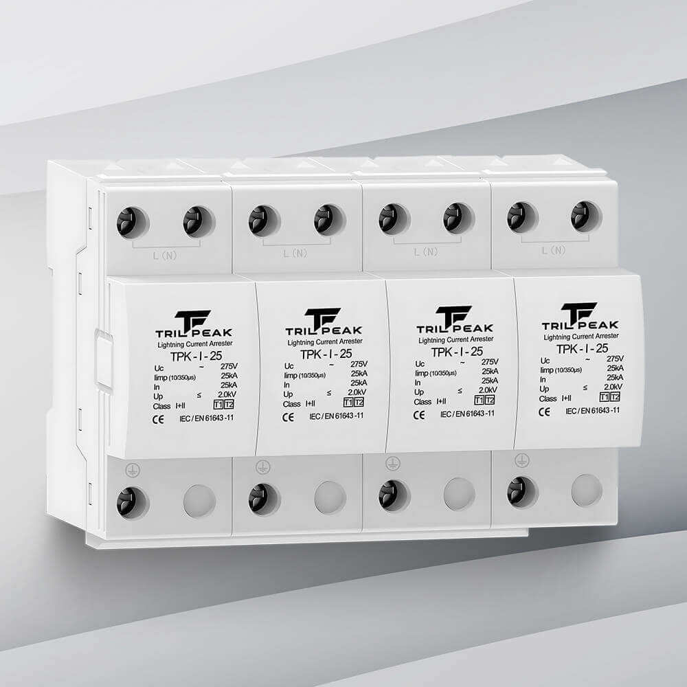
Need a Type 1+2 combined SPD for a compact panel or retrofit installation?
TrilPeak manufactures IEC 61643-11 Class I+II certified Type 1+2 combined SPDs — DIN rail, single and three phase, TN-S / TT / TN-C / IT earthing systems. OEM/ODM available, ships to 50+ countries.