How to Install a Surge Protector: SPD Wiring Guide (2026)
Quick Answer
Conductor size: Type 2 Surge Protective Device (SPD) → ≥6mm² Cu | Type 1 SPD → ≥16mm² Cu | DC PV SPD → ≥4mm² Cu.
50cm rule: Total lead length L1 + L2 + L3 ≤ 50cm. Every +10cm adds ~1kV residual surge voltage at equipment terminals.
Miniature Circuit Breaker (MCB) required: 32–63A Type B/C for Type 2 — 1-pole for single-phase, 3-pole for three-phase; 100–125A for Type 1. Never connect an SPD directly to the busbar without overcurrent protection.
DC solar: Use an IEC 61643-31 certified DC SPD only — never an AC SPD. Lead length ≤0.5m. A DC-rated gPV fuse is required.
This guide covers how to install a surge protector correctly for every common scenario: single-phase and three-phase Type 2 AC SPDs, Type 1 SPDs at the service entrance, and DC SPDs for solar Photovoltaic (PV) systems — with wiring diagrams, step-by-step procedures, and the conductor sizing and lead-length rules that determine whether the installed protection actually performs to its rated specification.
1. AC SPD Wiring — Type 2 Single Phase (230V) Installation
The Type 2 single-phase SPD is the standard installation for residential and commercial distribution boards, and knowing how to install a surge protector at this level comes down to three rules: correct mode for the earthing system, ≤50cm total lead length, and a dedicated 1-pole MCB. Getting any one of these three wrong reduces the installed protection level well below the device's rated specification.
1.1 Wiring Diagram — TN-S / TT System (1+1 Mode)
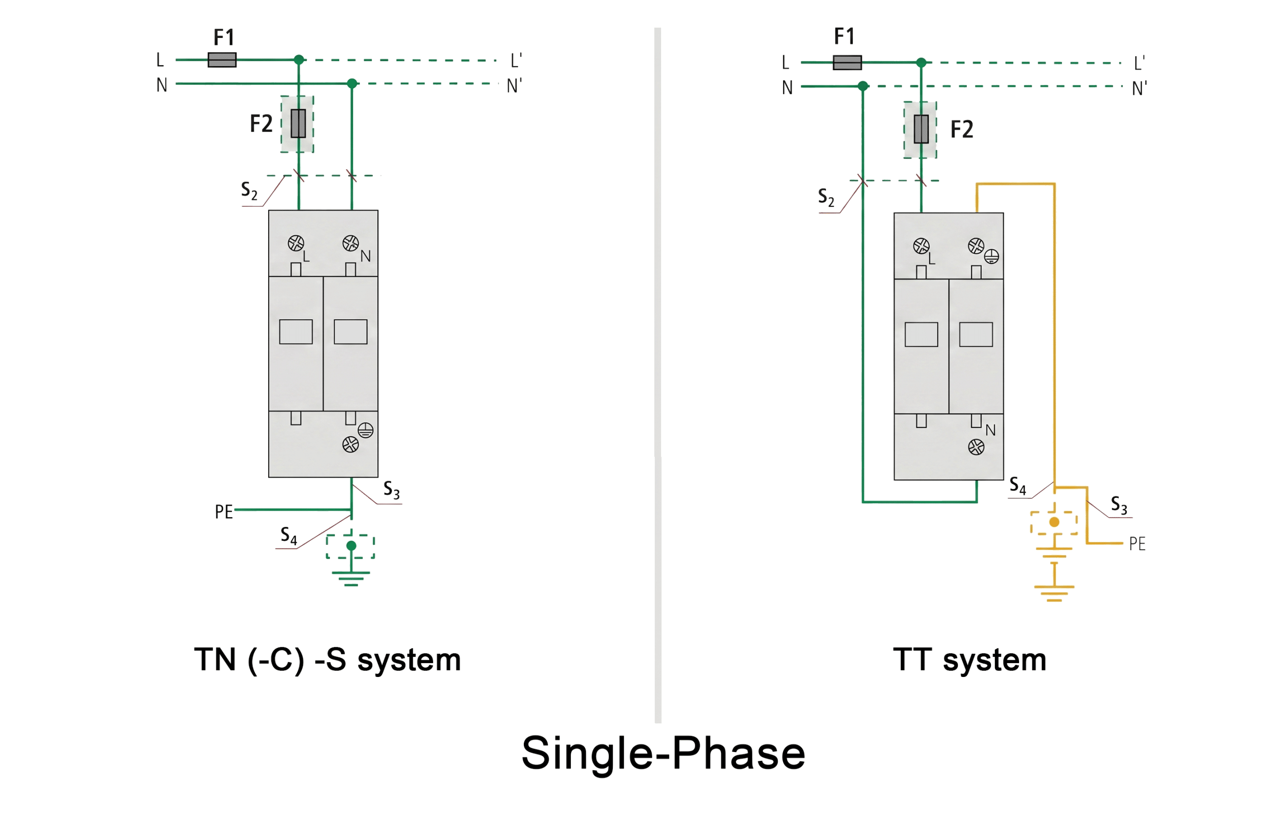
1.2 Step-by-Step: How to Install a Surge Protector (Type 2, Single Phase)
- Isolate and verify dead — Switch off the main incomer. Test all conductors with a calibrated voltage tester before touching any terminal.
- Mount SPD adjacent to busbars — Position on the DIN rail closest to the busbar entry. Measure the lead path before drilling — if total distance exceeds 50cm, choose a closer mounting point.
- Install a dedicated 1-pole MCB — Fit a 1-pole (single pole), 32–63A Type B or C MCB in the adjacent slot, on the L conductor only. This MCB is for the SPD only — do not share it with other circuits.
- Connect L (≥6mm² Cu) — From MCB output terminal → SPD L terminal. Keep this conductor as short and straight as possible.
- Connect N (≥6mm² Cu) — Direct from neutral busbar → SPD N terminal. No MCB on neutral.
- Connect PE (≥6mm² Cu) — Direct from earth busbar → SPD PE terminal. Straight run, no loops or coils.
- Restore power — check green indicator — Close MCB. Green status window = operational. Red = fault, investigate before commissioning.
The 50cm rule (IEC 60364-5-53): every 10cm of excess lead length adds approximately 1kV of residual surge voltage above the SPD's rated Up. A total lead length of 1m could raise a 2.5kV Up device to 3.5kV installed Up — exceeding the withstand rating of most distribution equipment.
TN-C earthing (PEN conductor): use 1+0 mode (1-pole SPD, L→PE only). N and PE are the same conductor — adding N–PE protection creates a fault path.
2. AC SPD Wiring — Type 2 Three Phase (400V) Installation
How to install a surge protector in a three-phase system follows the same 50cm rule and MCB requirements as single-phase, but pole count and mode depend on the earthing system — this is the most common specification error in industrial panel builds.
2.1 Wiring Diagram — TN-S System (3+1 Mode, 4-Pole)
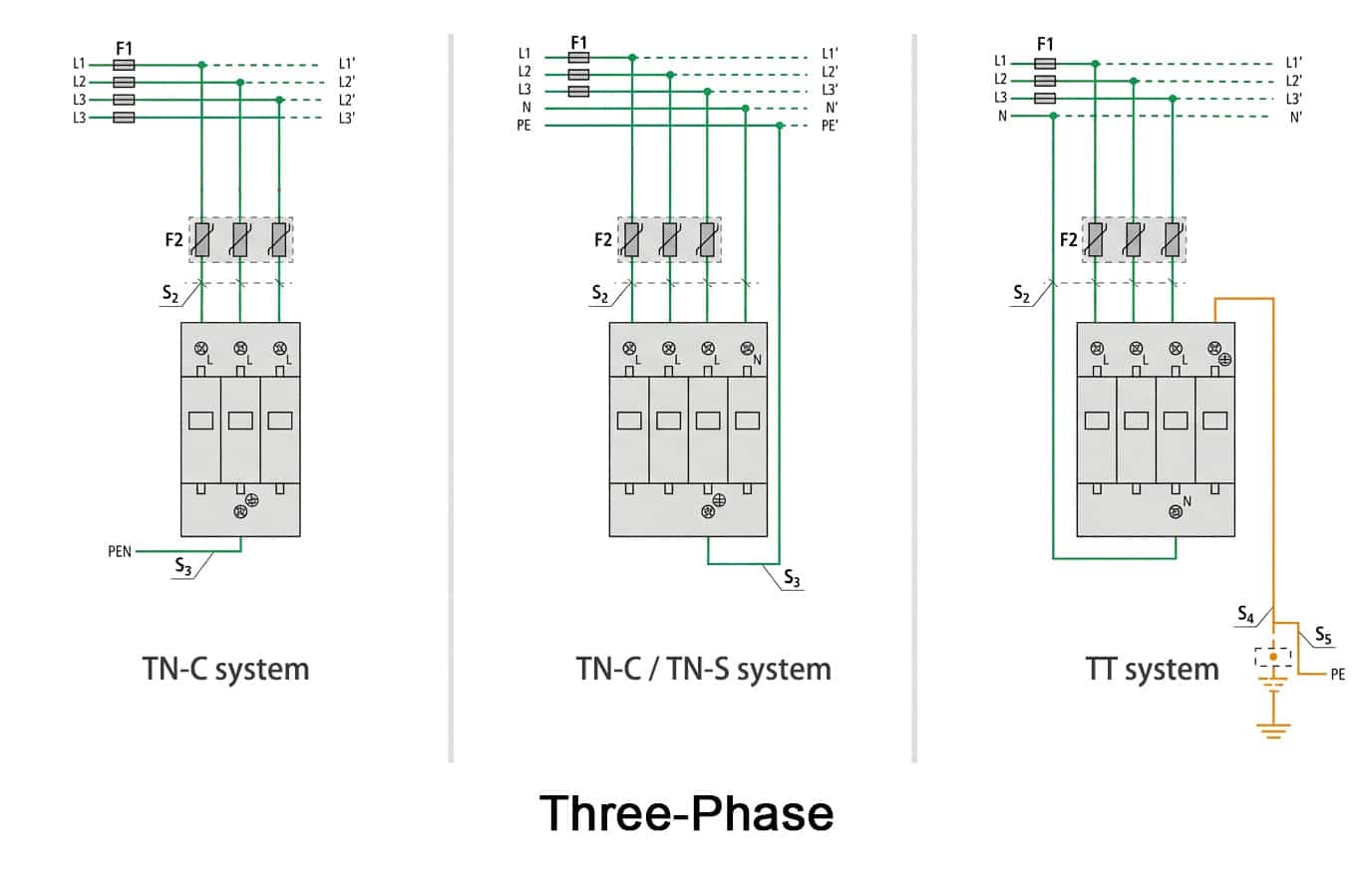
Most common 3-phase error: installing a 3-pole (3+0) SPD in a TN-S or TT building. The N→PE surge path is left completely unprotected. Always check the earthing system before selecting pole count.
2.2 How to Install a Surge Protector — Three Phase Steps
- Identify earthing system — TN-S or TT → 4-pole 3+1 or 4+0. TN-C → 3-pole 3+0.
- Isolate all five conductors — L1, L2, L3, N, and PE. Verify dead on all with a voltage tester.
- Mount SPD adjacent to busbars — Total lead path for all conductors must sum to ≤50cm.
- Install 3-pole MCB (32–63A) — Dedicated to SPD only.
- Connect L1, L2, L3 (≥6mm² Cu each) — From MCB output → SPD phase terminals.
- Connect N direct (≥6mm² Cu) — Neutral busbar → SPD N terminal (TN-S / TT only).
- Connect PE direct (≥6mm² Cu) — Earth busbar → SPD PE terminal, straight run.
- Restore and verify — Green status on all phases confirms correct installation.
3. Type 1 SPD — Service Entrance Installation
How to install a surge protector at the service entrance (Type 1) is mandatory whenever an external Lightning Protection System (LPS) is installed, per IEC 62305-4, because it handles partial direct lightning current (10/350µs waveform) that would destroy a standard Type 2 device.
3.1 Key Differences from Type 2
| Parameter | Type 1 | Type 2 |
|---|---|---|
| Conductor size | ≥16mm² copper | ≥6mm² copper |
| MCB / fuse | 100–125A, Type B or gG fuse | 32–63A, Type B/C |
| Position | Main service entrance, upstream of main MCB | Main distribution board |
| Test waveform | 10/350µs, Iimp ≥ 12.5kA | 8/20µs, In ≥ 20kA |
| Required when | External LPS (lightning rods) installed | Always recommended |
Note: a Type 1+2 combined SPD installs as a single device at the service entrance and saves panel space — recommended for new installations where an external LPS is present. It eliminates the 10m separation requirement between Type 1 and Type 2 stages that applies when they are installed as separate devices.
10m separation rule (IEC 61643-12): when Type 1 and Type 2 SPDs are in separate panels, ≥10m of cable must separate them for energy coordination. Without this, both devices clamp simultaneously and the Type 2 is overloaded. A Type 1+2 combined device eliminates this requirement entirely.
4. DC SPD — Solar PV Wiring & Installation
How to install a surge protector for DC solar differs from AC in three critical ways: it must be IEC 61643-31 certified, lead length tightens to ≤0.5m, and a DC-rated fuse — not an AC MCB — is required. For the full DC SPD selection methodology beyond wiring, see TrilPeak's solar surge protection guide.
4.1 Wiring Diagram — PV Combiner Box or Inverter DC Input
4.2 How to Install a Surge Protector (DC Solar) — Step by Step
- Isolate and shade the array — Open the DC isolator and shade or disconnect string fuses. PV arrays generate voltage in daylight — always verify zero voltage with a DC multimeter before working.
- Confirm SPD certification — Must be IEC 61643-31 (not IEC 61643-11). Confirm Ucpv ≥ 1.2 × Voc(max) for the string voltage. For 1000V strings: Ucpv ≥ 1000V.
- Install DC-rated gPV fuse — Standard AC MCBs must not be used. DC arcs do not self-extinguish. Use a gPV-rated fuse per IEC 60269-6.
- Connect PV+ (≥4mm² Cu) — Via gPV fuse → SPD positive terminal. Observe polarity.
- Connect PV− (≥4mm² Cu) — Direct to SPD negative terminal.
- Connect PE (≥4mm² Cu) — Shortest direct route to chassis earth busbar (target ≤0.25m for this leg).
- Verify total lead length ≤0.5m — Tighter than the AC rule because DC arc extinction requires lower inductance in the clamping path.
- Restore and check — Close the DC isolator; verify the green status indicator.
5. Conductor Sizing & MCB: Quick Reference Table
Every SPD installation is governed by the same three parameters — minimum conductor size, MCB or fuse rating, and maximum lead length — and the required values scale directly with the SPD type. The table below consolidates all four scenarios covered in this guide.
| SPD Type | Min. Conductor (Cu) | MCB / Fuse | Max. Lead Length | Standard |
|---|---|---|---|---|
| Type 1 | ≥16mm² | 100–125A, Type B or gG fuse | ≤50cm total | IEC 60364-5-53 |
| Type 2 (single-phase) | ≥6mm² | 1-pole, 32–63A Type B or C | ≤50cm total | IEC 60364-5-53 |
| Type 2 (three-phase) | ≥6mm² | 3-pole, 32–63A Type B or C | ≤50cm total | IEC 60364-5-53 |
| Type 3 | ≥2.5mm² | Existing circuit MCB | ≤10m from Type 2 | IEC 60364-5-53 |
| DC SPD (PV) | ≥4mm² | DC-rated gPV fuse | ≤0.5m total | IEC 61643-31 |
6. 5 Mistakes That Kill SPD Performance When You Install a Surge Protector
Five installation mistakes account for most of the real-world cases where a correctly specified SPD still fails to protect connected equipment. Each one is a wiring or specification error, not a product defect.
- Lead length over 50cm — SPD mounted far from the busbar with looped or coiled conductors. Installed Up rises dramatically — protection may be near zero for sensitive equipment. Fix: reposition the SPD adjacent to the busbar, or use a sub-enclosure at the service entry.
- No dedicated MCB — SPD connected directly to the busbar. When the MOV fails in short-circuit mode, no device trips to isolate it, creating a fire risk in the wiring. Fix: always fit a dedicated 32–63A Type B MCB — 1-pole for single-phase, 3-pole for three-phase.
- 3-pole SPD in a TN-S panel — N→PE path completely unprotected. Surges via neutral reach all connected equipment. Fix: use 4-pole 3+1 for TN-S, 4+0 for TT.
- AC SPD on a DC solar circuit — IEC 61643-11 devices cannot extinguish DC arcs and will fail catastrophically under surge. Fix: use an IEC 61643-31 certified DC SPD with Ucpv rated for the string voltage.
- Uc = nominal voltage (e.g. Uc = 230V) — No margin for temporary overvoltages (TOV), causing rapid MOV degradation. Fix: Uc ≥ 1.1 × Un. For 230V systems: Uc ≥ 255V. For 480V North American systems: Uc ≥ 320V.
7. Frequently Asked Questions: How to Install a Surge Protector Correctly
7.1 How do you wire a surge protector to a distribution panel?
To install a surge protector correctly at the distribution board: mount the SPD on the DIN rail adjacent to the busbars. Install a dedicated 1-pole, 32–63A MCB between the live busbar and the SPD's L terminal. Connect N direct to the neutral busbar. Connect PE direct to the earth busbar. Total lead length must not exceed 50cm. Use ≥6mm² copper throughout. After wiring, close the MCB and confirm the green status indicator.
7.2 What is the 50cm rule for SPD installation?
The most critical rule when you install a surge protector is the 50cm rule (IEC 60364-5-53): total lead length — supply plus neutral plus earth wire — must not exceed 50cm. For an 8/20µs surge at 8kA, each metre adds approximately 1,000V above the SPD's rated Up. At 50cm, the rise is roughly 500V — acceptable for OVC Category II equipment. Longer leads significantly reduce effective protection.
7.3 Does a surge protector need its own circuit breaker?
Yes. A Type 1 or Type 2 SPD must have a dedicated MCB or fuse — never connect it directly to the main busbar without overcurrent protection. When MOV elements fail in short-circuit mode, the dedicated MCB trips and isolates the SPD without affecting the rest of the panel. Use 32–63A Type B for Type 2 — 1-pole for single-phase, 3-pole for three-phase; 100–125A for Type 1. Type 3 devices use the existing circuit MCB.
7.4 How to install a 3-phase surge protector?
How to install a surge protector in three-phase: first identify the earthing system — TN-S uses 3+1 mode; TT uses 4+0 mode; TN-C uses 3+0 mode. Isolate all five conductors and verify dead. Mount the SPD adjacent to the busbars and install a 3-pole 32–63A MCB. Connect L1/L2/L3 from the MCB (≥6mm² Cu each), and connect N and PE direct. Total lead length must stay ≤50cm. Restore power and check the green indicator on all phases.
7.5 How to install a DC surge protector for solar panels?
How to install a surge protector on DC solar: use only an IEC 61643-31 certified DC SPD. Connect PV+ via a gPV fuse to the SPD positive terminal. Connect PV− direct to the SPD negative terminal. Connect PE to the chassis earth busbar. Total lead length must stay ≤0.5m, and Ucpv must be ≥1.2 × Voc(max) of the string. Verify zero DC voltage before working and check the green status indicator after restoration.
7.6 What size wire should I use for a surge protector?
Conductor size per IEC 60364-5-53: Type 2 SPD requires ≥6mm² Cu; Type 1 SPD requires ≥16mm² Cu; Type 3 SPD requires ≥2.5mm² Cu; DC PV SPD requires ≥4mm² Cu. Never use smaller conductors — undersized wiring overheats under surge current and can disconnect the SPD at the exact moment it is most needed.
7.7 What is the difference between Type 1 and Type 2 SPD installation?
Type 1 SPDs install at the main service entrance, are mandatory when external lightning rods are present per IEC 62305-4, and require ≥16mm² conductors with a 100–125A MCB. Type 2 SPDs install at the distribution board with ≥6mm² conductors and a 32–63A MCB (1-pole for single-phase, 3-pole for three-phase). Both follow the ≤50cm lead-length rule. When Type 1 and Type 2 are installed as separate devices, ≥10m of cable separation is required between them — or a Type 1+2 combined device can be used instead.
7.8 How do I know if my surge protector is installed correctly?
Check four things after installation: the status indicator shows green, confirming the MOV elements are operational; the protection MCB has not tripped immediately on closure; the voltage between the SPD's L and PE terminals reads approximately the system L–PE voltage (230V for IEC single-phase); and the physical lead length measures ≤50cm in total. Document the installation date for future maintenance records.
8. Conclusion: Three Rules Govern Every SPD Installation
Regardless of SPD type — Type 1, Type 2, or DC solar — how to install a surge protector correctly comes down to the same three constraints: select the correct mode and pole count for the earthing system in use, size the conductors to the type's minimum copper cross-section, and keep total lead length within the standard's limit (50cm for AC Type 1/Type 2, 0.5m for DC PV). A device that meets every datasheet specification will still under-perform its rated Up if any one of these three rules is violated during installation, which is why the five mistakes in Section 6 — not product defects — account for most real-world SPD protection failures.
Related Resources & Standards
Need full wiring diagrams and datasheets for your next SPD order?
TrilPeak supplies Type 1, Type 2, Type 1+2 combined, and IEC 61643-31 DC SPDs for all installation types, with full wiring diagrams and datasheets included with every order. CE certified · IEC 61643-11 · engineering reply within 24h.