Neutral Bar vs Grounding Bar: What Every Electrical Installer Needs to Know
Quick Answer
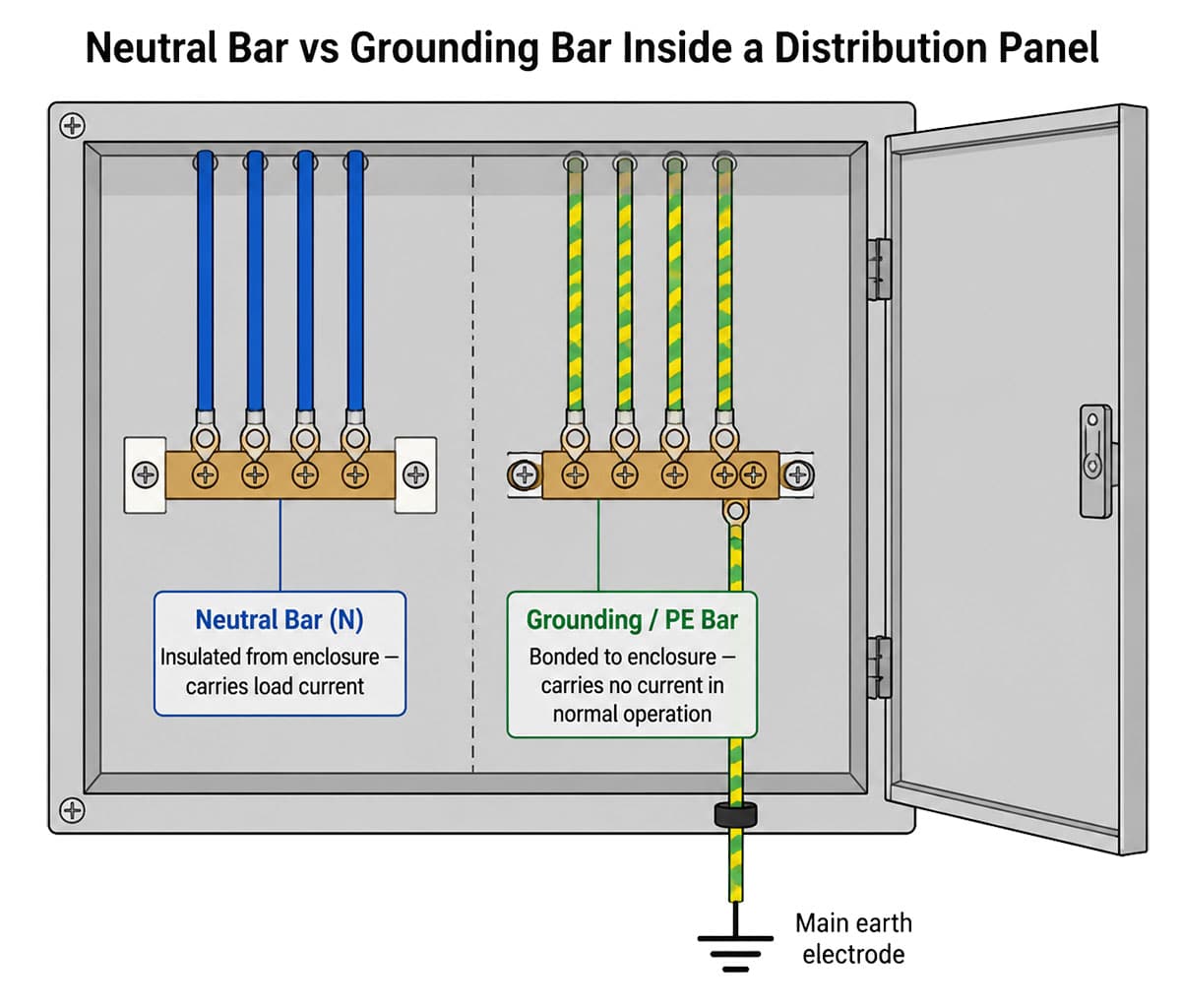
Neutral bar (N bar): Carries current-carrying neutral conductors back to the supply source. Connected to the neutral point of the supply transformer. Carries load current during normal operation. Must be insulated from the enclosure in TN-S and TT systems.
Grounding bar / Earth bar (PE bar): Connects all exposed conductive parts and protective earth conductors to the main earthing terminal. Does not carry load current during normal operation. Bonded directly to the panel enclosure.
Why it matters for SPDs: Surge protective devices connect between live conductors, neutral, and PE. If the N bar and PE bar are incorrectly bonded or confused, the SPD's discharge path to earth is compromised — the device will appear to be installed correctly but will fail to clamp surges effectively, or will cause nuisance tripping under normal conditions.
For panel builders and electrical installers, the distinction between the neutral bar and the grounding bar is foundational — but it is also one of the most consequential wiring decisions in a distribution panel. Getting it wrong does not just affect the panel's normal operation; it directly determines whether every piece of protection equipment downstream — including surge protective devices — actually works. This guide covers the technical distinction, the IEC wiring rules, and why correct N/PE separation is the prerequisite for effective surge protection.
1. What Is a Neutral Bar?
The neutral bar (N bar) is a busbar inside a distribution panel that serves as the common connection point for all neutral conductors, carrying load current back to the supply during normal operation. In a low-voltage AC system, the neutral conductor carries the return current from loads back to the neutral point of the supply transformer. Under balanced three-phase load conditions, the neutral current is theoretically zero — but in real installations with unbalanced loads, single-phase circuits, or non-linear loads such as Variable Frequency Drives (VFDs), switch-mode power supplies, and LED drivers, the neutral carries significant current continuously.
Because the neutral bar carries load current, it must be treated as a live conductor for safety purposes in most system configurations. In TN-S and TT systems (defined by IEC 60364-1), the neutral bar must be insulated from the panel enclosure — it is not bonded to earth at the distribution panel level. The neutral-to-earth bond exists only at one point in the system: the supply transformer's star point or the main earthing point of the installation.
1.1 Neutral Bar in Different Earthing Systems
- TN-S system: Neutral (N) and protective earth (PE) are separate conductors throughout. Neutral bar is insulated from enclosure. PE bar is bonded to enclosure. The two busbars must not be connected at the distribution panel.
- TN-C system: Neutral and protective earth are combined in a single PEN conductor. A single combined N/PE bar is used — but this system is generally not permitted in new installations under IEC 60364 and is encountered mainly in older infrastructure.
- TN-C-S system: PEN conductor upstream splits into separate N and PE at the main distribution board. At the split point, N and PE are bonded — but only at this one point. All downstream boards treat N and PE as separate conductors.
- TT system: Supply neutral is earthed at the transformer, but the installation's exposed parts are connected to a separate independent earth electrode. Neutral bar is insulated from the PE bar in all distribution panels.
2. What Is a Grounding Bar (PE Bar)?
The grounding bar — also called the earth bar, PE bar, or protective earth busbar — is the connection point for all protective earth (PE) conductors in the panel, providing a low-impedance path to earth for fault current. If a live conductor contacts an exposed metal part of any connected equipment, sufficient fault current must flow through this path to trip the upstream overcurrent protection and de-energise the fault.
Unlike the neutral bar, the PE bar carries no current during normal operation. It only carries current during a fault condition, when it must carry enough current to operate the protective device quickly — typically within 0.4 seconds for final circuits in IEC 60364-4-41. The PE bar is bonded directly to the panel enclosure and connected to the main earthing terminal of the installation via the main protective conductor.
2.1 What Connects to the PE Bar
- Protective earth conductors (green/yellow) from all connected equipment and circuits
- Earth conductor from the panel enclosure itself
- PE terminal of every surge protective device installed in the panel
- Equipotential bonding conductors connecting metallic services (water pipes, structural steel) at the installation's main earthing point
- Earth terminal of any DIN-rail mounted SPD, RCD, or earthing module
3. Neutral Bar vs Grounding Bar: 6 Key Differences
The neutral bar and grounding bar differ across six key parameters — function, current-carrying behaviour, enclosure bonding, conductor colour, earth connection point, and how the SPD connects to each.
| # | Parameter | Neutral Bar (N) | Grounding Bar (PE) |
|---|---|---|---|
| 1 | Function | Returns load current to supply neutral point | Provides fault current path to earth |
| 2 | Current during normal operation | Carries load current (up to full circuit rating) | Carries no current (zero under normal conditions) |
| 3 | Connection to enclosure | Insulated from enclosure (TN-S, TT systems) | Bonded directly to enclosure |
| 4 | Conductor colour | Blue (IEC standard) | Green/yellow (IEC standard) |
| 5 | Earth connection point | Earthed only at supply transformer star point | Connected to main earth terminal at every panel |
| 6 | SPD connection | SPD neutral terminal connects here (L-N protection mode) | SPD PE terminal connects here (surge discharge path to earth) |
4. Why N/PE Separation Is the Foundation of Effective Surge Protection
The correct separation of the neutral bar and grounding bar is not just a compliance requirement — it is the physical prerequisite for a surge protective device to function as specified. Here is why.
When a surge event occurs, the SPD must divert the transient current from the live conductor (or neutral conductor) to the protective earth as quickly as possible — typically within 25 nanoseconds for a quality DIN-rail SPD. This diversion only works if the PE terminal of the SPD has a direct, low-impedance, uninterrupted path to the main earth electrode.
If the N bar and PE bar are incorrectly bonded together at the distribution panel — creating an unwanted N-PE connection downstream of the main earthing point — several problems arise simultaneously:
- Neutral current flows into the PE conductor network, creating touch voltage on exposed metal parts of equipment
- The SPD's N-PE protection mode is short-circuited — the device cannot clamp the N-PE voltage because N and PE are already connected
- Residual current devices (RCDs) upstream of the panel will see imbalanced current and trip nuisance faults
- In TT systems specifically, an N-PE bond at the wrong point creates a parallel earth path that defeats the TT system's earth fault detection entirely
Note: IEC 60364-5-54 explicitly prohibits connecting the neutral conductor to the protective earth conductor at any point other than the system's designated earthing point. Multiple N-PE bonds in an installation are a code violation regardless of which panel they occur in.
5. How SPDs Connect to Both Bars
A correctly installed surge protective device in a three-phase TN-S system uses multiple protection modes simultaneously, connecting across different conductor combinations to intercept surges regardless of which conductor they appear on. This is why both the neutral bar and the PE bar are relevant to SPD installation.
5.1 Protection Modes in a TN-S System
- L-PE mode: Between each line conductor and the PE bar — clamps line-to-earth surges
- N-PE mode: Between the neutral bar and the PE bar — clamps neutral-to-earth surges generated by asymmetric transients
- L-N mode: Between line conductors and the neutral bar — clamps differential mode surges
For the N-PE mode to function, the neutral bar and PE bar must be correctly separated and individually accessible. The SPD's neutral terminal connects to the N bar; the SPD's PE terminal connects to the PE bar. If the two bars are bonded together at the panel, the N-PE varistor inside the SPD is permanently short-circuited and provides no protection.
5.2 Lead Wire Length — The Installation Rule Most Often Ignored
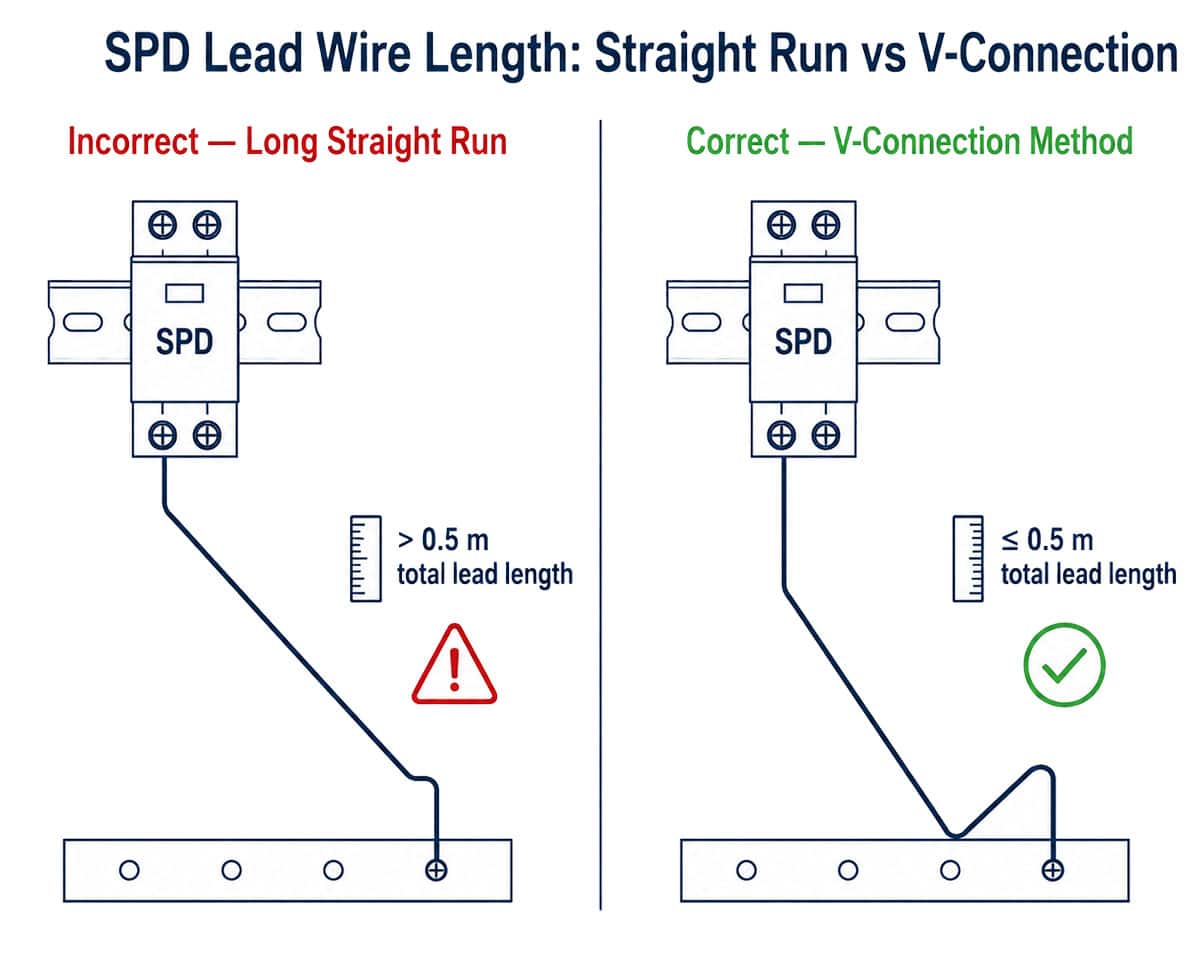
Once the N/PE separation is correct, the next most critical installation parameter is the length of the conductors connecting the SPD terminals to the N bar and PE bar. The total combined length of the line-side lead and the PE-side lead must not exceed 0.5 metres. Every additional centimetre of conductor adds inductance, and inductance adds voltage during the fast rise time of a surge event. A device rated at Up = 1.5 kV can allow 3 kV or more to reach the protected equipment if the connecting leads are too long — the rated protection level on the datasheet becomes meaningless.
Where the panel layout makes short leads difficult, use the V-connection method: route both conductors in a V-shape that minimises total path length, even if it means bending conductors back toward the SPD terminals rather than running them straight to the busbar.
6. Why Correct Wiring Is Only Half the Answer: SPD Quality Matters
Correct N/PE separation and proper lead wire management are necessary conditions for surge protection to work — but they are not sufficient, since the SPD itself must be built to the specification it claims. Understanding what determines SPD build quality helps engineers and panel builders make informed procurement decisions and evaluate whether a device will perform as rated over its service life.
6.1 MOV Component Type: Surge-Rated vs General-Purpose
The Metal Oxide Varistor (MOV) is the core protective element in a DIN-rail SPD. Two fundamentally different component types exist, and the distinction determines how the device behaves both during a surge event and during the long periods of normal grid operation between surge events.
A surge-rated MOV is specifically engineered for impulse current absorption. Its energy capacity, clamping voltage stability under repeated high-current pulses, and thermal characteristics are all designed around the 10/350 µs and 8/20 µs waveforms defined in IEC 61643-11.
A general-purpose varistor is designed for a different application: continuous low-current voltage regulation in power supplies and electronics. Its impulse energy absorption capacity is a fraction of a surge-rated MOV's.
TrilPeak Engineering Note: An SPD does not only activate during surge events — it carries a small continuous leakage current throughout its service life under normal grid voltage. For a surge-rated MOV, this continuous low-level stress is within its design parameters and causes predictable, gradual degradation over years. For a general-purpose varistor operating in the same conditions, the thermal load from this continuous leakage current is disproportionately high relative to its design rating — the component runs warmer, degrades faster, and reaches end-of-life significantly earlier. The external appearance of the device does not change during this process. The thermal protection circuit may not trigger because the failure mode is gradual thermal degradation rather than a discrete overcurrent event. The result is an SPD that looks operational but has lost a significant portion of its clamping capacity — invisible to any external inspection.
6.2 Enclosure Material: Flame Retardancy
SPDs installed in distribution panels operate in thermally constrained enclosures alongside other electrical equipment. The enclosure material's response to heat is a critical safety parameter. IEC 61643-11 requires flame-retardant enclosure material — the industry standard is PA66 UL94 V-0, which self-extinguishes within 2 seconds of ignition source removal.
TrilPeak Engineering Note: The difference between a UL94 V-0 rated enclosure and an unrated or recycled-material enclosure is not visible under normal conditions — both are opaque plastic, both look identical in a product photograph or on a shelf. The difference becomes consequential only when the device reaches end-of-life under thermal stress. A V-0 enclosure contains the failure as a localised, self-extinguishing event. An unrated enclosure in the same scenario may ignite and sustain combustion inside a closed distribution panel — converting an SPD replacement event into a panel fire. This is not a theoretical risk: distribution panels are enclosed, poorly ventilated, and typically unattended. The material cost difference between V-0 rated PA66 and unrated recycled plastic is small; the consequence difference under thermal failure is not.
6.3 Internal Busbar Material: Copper vs Iron
The internal busbars connecting SPD terminals to the MOV assembly conduct surge current during a discharge event. Copper is the standard material for this application — its electrical conductivity ensures low resistive losses and minimal heat generation at surge current levels.
TrilPeak Engineering Note: Iron busbars have approximately 17% of copper's electrical conductivity. At the impulse currents an SPD handles during a surge event — 20 kA, 40 kA, or higher for Type 1 devices — this conductivity difference translates directly into higher resistive heating inside the device. More practically relevant for long-term service is corrosion: iron corrodes progressively in humid environments, and the corrosion forms at the contact interfaces between the busbar and the MOV terminals — exactly where low contact resistance is most critical. In coastal installations, rooftop solar enclosures, and any outdoor panel in a humid climate, iron busbar corrosion is a progressive degradation mechanism that increases internal resistance over months and years. The device continues to appear functional; its ability to discharge surge current at rated capacity decreases. Copper does not corrode in the same way and maintains stable contact resistance across the service life of the device.
6.4 Status Indicator Reliability
The visual status indicator (green = functional, red = replace) is the primary field maintenance tool for SPD monitoring in installations without remote SCADA integration. Its value depends entirely on whether it is directly wired to the thermal protection mechanism — changing state when the MOV disconnects — or whether it is wired only to indicate power supply presence.
TrilPeak Engineering Note: An indicator wired to power presence rather than MOV status will remain green after the protective element has thermally disconnected. In practice this means a panel that has been de-energised and re-energised after a surge event — a common maintenance sequence — will show all SPDs as green even if one or more thermal disconnects have operated. The failed device is indistinguishable from a functional one by visual inspection. For installations that rely on visual inspection as the primary maintenance method (the majority of commercial and industrial panels), a cosmetic status indicator provides no maintenance value and creates a false record of protection status. The indicator's connection topology — whether it is genuinely linked to the thermal disconnect or simply to supply voltage — is not identifiable from the outside of the device.
6.5 Verification: Third-Party Test Certificates
IEC 61643-11 certification can be demonstrated through a manufacturer's self-declaration of conformity (DoC) or through third-party laboratory testing by an accredited body such as DEKRA, TÜV, SGS, or Bureau Veritas. The test certificate should reference the specific standard version (IEC 61643-11:2011+AMD1:2017), list all tested parameters (Iimp or In, Imax, Up, Uc), and identify the exact product model tested.
Requesting the third-party test certificate — rather than relying on the CE mark or DoC alone — is the most reliable way to confirm that a device's rated parameters have been independently verified on the actual product, not extrapolated from component data or tested on a pre-production sample.
7. Panel Installation Checklist: N Bar, PE Bar, and SPD
Use this checklist before, during, and after SPD installation to confirm both the panel wiring and the short-circuit protection device selection are correct.
7.1 Before Installing the SPD
- Confirm the earthing system type: TN-S, TN-C-S, TN-C, or TT
- Verify the N bar is insulated from the enclosure (TN-S and TT systems)
- Verify the PE bar is bonded to the enclosure
- Confirm there is no N-PE bond at this panel (unless this is the designated system earthing point)
- Check that the main earth conductor to the PE bar is correctly sized and has a low-impedance connection to the earth electrode
7.2 During SPD Installation
- Connect SPD neutral terminal to the N bar — not to the PE bar
- Connect SPD PE terminal to the PE bar — not to the N bar
- Keep total lead wire length (line-side + PE-side) ≤ 0.5 metres
- Use V-connection method if straight runs exceed 0.5 m
- Verify the upstream Short-Circuit Protection Device (SCPD) is correctly specified — see Section 7.4 below
- Connect remote signalling contacts to the building management or monitoring system if available
7.3 After Installation
- Verify the SPD status indicator shows green after energisation
- Check for any nuisance RCD tripping — if present, investigate for inadvertent N-PE bonds
- Record the installation date, SPD model, and panel location for maintenance scheduling
- Schedule the first visual inspection — annually or after any significant lightning event in the area
7.4 SCPD Selection: Fuse or Circuit Breaker?
IEC 61643-11 Section 7.7 requires every SPD installation to include an upstream Short-Circuit Protection Device (SCPD) — a device that disconnects the SPD from the supply in the event of an SPD internal short-circuit fault. Two types of SCPD are used in practice: fuses and miniature circuit breakers (MCBs). They are not interchangeable for all SPD types, and the choice has practical implications for installation cost and maintenance.
Fuses (gG or aM type) are the most common SCPD choice for SPD installations in international projects. They are lower cost, require no calibration, and provide reliable short-circuit protection. The key requirement is that the fuse type and rating must be within the limits specified in the SPD manufacturer's datasheet — a fuse rated too high will not protect the SPD under fault conditions; a fuse rated too low may blow during a legitimate surge discharge event. gG fuses (general purpose, full-range) are suitable for most Type 2 SPD applications. The fuse rating is typically 25 A to 125 A depending on the SPD's In rating and the installation's supply current.
Miniature circuit breakers (MCBs) are commonly used in domestic and commercial panel installations where fuse holders are not already present, and in markets where circuit breaker coordination is the standard design practice. However, not all MCBs are suitable for use upstream of a Type 1 SPD: the 10/350 µs impulse current waveform of a lightning event can cause a standard MCB to open during a legitimate surge discharge, leaving the downstream installation unprotected after the event. For Type 1 and Type 1+2 SPDs, the SPD manufacturer's datasheet specifies which MCB characteristics (typically B or C curve, minimum breaking capacity) are acceptable. Always verify MCB compatibility against the datasheet before specifying.
Note: TrilPeak SPD datasheets specify the maximum SCPD rating and acceptable device types for each product in the range. For installations where a separate SCPD device is not preferred, TrilPeak's surge backup protector series integrates the SCPD function within the SPD assembly, simplifying panel design and reducing component count.
For detailed guidance on when to replace a surge protector and what the status indicators mean in practice, see our replacement guide. For MCB and fuse coordination rules in full, see our circuit breaker vs SPD coordination guide.
8. Grounding and Earthing Accessories for Panel Builders
Correct surge protection performance depends entirely on the quality of the earthing system it connects to — a Type 2 SPD with Up = 1.5 kV and In = 40 kA cannot deliver its rated performance if the PE bar has a high-impedance connection to earth. The SPD will attempt to divert surge current, but the voltage across the earth impedance will add directly to the clamping voltage seen by the protected equipment.
TrilPeak's grounding and earthing accessories range includes DIN-rail earth busbars, equipotential bonding terminals, and earthing clamps designed for integration with SPD installations in commercial and industrial distribution panels. Correct earthing system design is the foundation that makes surge protection work — not an afterthought.
For a full technical guide on the relationship between earthing systems and SPD selection, including how TN-S, TN-C, and TT systems require different SPD configurations, see our whole-building surge protection guide.
9. Frequently Asked Questions
9.1 Can the neutral bar and grounding bar be connected together in a sub-panel?
No — in a TN-S or TT system, the neutral bar and PE bar must not be bonded together at any sub-distribution panel. The N-PE bond is only permitted at the designated system earthing point — typically the main distribution board or the supply transformer's star point. Bonding N and PE at a sub-panel creates a parallel earth return path for neutral current, generating touch voltage on equipment enclosures and causing nuisance RCD tripping. It also compromises SPD N-PE protection mode.
9.2 How can I tell if my panel has the neutral bar and grounding bar confused?
The clearest field indicator is nuisance RCD tripping with no apparent load fault — this is a classic symptom of neutral current flowing in the PE conductor due to an inadvertent N-PE bond. Other indicators: the PE bar is not bonded to the panel enclosure (it should be), or neutral conductors (blue) are connected to the bar that is bonded to the enclosure. A clamp meter on the PE conductor between two panels showing significant current flow under normal load conditions confirms the problem.
9.3 Does it matter which bar the SPD neutral terminal connects to?
Yes — critically. The SPD's neutral terminal must connect to the neutral bar (insulated from enclosure), and the PE terminal must connect to the PE bar (bonded to enclosure). Reversing these connections or connecting both to the same bar defeats the SPD's N-PE protection mode entirely. It may also create a permanent low-impedance path between neutral and earth that disrupts the entire installation's earthing system.
9.4 Why does lead wire length affect SPD performance?
Every conductor has inductance — approximately 1 µH per metre for typical installation wire. During a surge event, the voltage across an inductance equals L × (di/dt). Lightning-induced surges have extremely fast rise times (di/dt), so even a short conductor adds significant voltage in series with the SPD's clamping voltage. A 0.5 m total lead length adds roughly 0.5 µH of inductance; at a surge rise rate of 1 kA/µs, this adds 500 V on top of the SPD's rated Up. At 1 m of leads, the added voltage doubles. This is why the ≤ 0.5 m total lead wire rule is not a guideline — it is a performance requirement.
9.5 How do I verify an SPD is genuinely IEC 61643-11 certified?
Request the test certificate from an accredited third-party laboratory — DEKRA, TÜV, SGS, Bureau Veritas, or equivalent. The certificate should reference the specific standard version (IEC 61643-11:2011+AMD1:2017), list the tested parameters (Iimp or In, Up, Uc, and Imax), and name the specific product model tested. A CE mark or a manufacturer's self-declaration of conformity alone is not sufficient evidence of genuine IEC 61643-11 certification. Third-party laboratory test reports are the only reliable verification.
9.6 What is the difference between a neutral link and a neutral bar?
A neutral link is a removable connection between the neutral conductor and earth, used in certain metering and isolation configurations to allow the neutral to be disconnected for testing. A neutral bar is the permanent busbar to which all neutral conductors in a panel are terminated. In practice, the terms are sometimes used interchangeably, but in IEC-standard panel design they are distinct components with different functions. For SPD installation purposes, the relevant component is the neutral bar — the permanent busbar that all circuit neutral conductors connect to.
10. Conclusion
Neutral bar vs grounding bar ultimately comes down to two fundamentally different functions in a distribution panel — one carries operating current, the other provides a fault and surge discharge path. Keeping them correctly separated per IEC 60364 is the prerequisite for effective surge protection: an SPD installed in a panel with an incorrect N-PE bond will fail to perform its rated function regardless of how well it is specified on paper.
But correct wiring is only half the answer. The SPD itself must be built to the standard it claims. The gap between a genuinely IEC 61643-11 certified device — with surge-rated MOV components, UL94 V-0 enclosure material, copper internal busbars, and a status indicator directly linked to the thermal protection mechanism — and a low-cost substitute that passes visual inspection but fails under real surge conditions is not visible from the outside. It only becomes apparent when the protection is needed.
For panel builders and electrical contractors specifying SPDs, the combination of correct N/PE panel wiring and verified SPD quality is what determines whether the installation actually protects the equipment it serves.
Related Resources & Standards
Need IEC 61643-11 certified SPDs with verified surge-rated MOV components?
TrilPeak manufactures surge protective devices with in-house MOV production, PA66 UL94 V-0 enclosures, and copper internal busbars — built to perform when it matters. CE certified · IEC 61643-11 · engineering reply within 24h.