
MOV Surge Protector Working Principle: Clamping Voltage, Type 1/2/3 Protection Explained
Quick Answer: How Does a Surge Protection Device Work?
A Surge Protective Device (SPD) works by connecting in parallel with the power supply and remaining electrically inactive during normal operation. When a transient overvoltage occurs — from a lightning strike, grid switching, or inductive load switching — the SPD's core component, a Metal Oxide Varistor (MOV), detects the voltage spike and switches from high resistance to low resistance in nanoseconds. It clamps the voltage to a safe limit called the voltage protection level (Up) — also known as the clamping voltage — and simultaneously diverts surge current away from connected equipment into the grounding system. Once the transient passes, the MOV returns to its high-resistance standby state and normal operation resumes, with no power interruption to the protected circuit. This is the fundamental surge protection device working principle behind every IEC 61643-11 certified SPD.
If you're specifying surge protection for an industrial installation, solar PV system, or commercial facility, understanding how an MOV surge protector actually works is the foundation for selecting the right device and verifying that a supplier's claims are technically credible. This guide covers the complete working principle of the MOV surge protector — from the physics of the zinc oxide (ZnO) grain boundaries to the engineering logic of cascaded three-stage protection — using data from the Institute of Electrical and Electronics Engineers (IEEE) standard IEEE C62.41 and IEC 61643-11.
1. How Does a Surge Protector Work — and What Does an SPD Actually Do?
A surge protective device — at its core, an MOV surge protector — does one specific job: it limits transient overvoltages to a level that connected equipment can safely withstand. It does not interrupt power, filter harmonics, regulate steady-state voltage, or provide backup power — those functions belong to circuit breakers, power conditioners, and Uninterruptible Power Supplies (UPS) respectively.
The key distinction engineers must internalize: a circuit breaker responds to sustained overcurrent in milliseconds to seconds; an MOV surge protector responds to microsecond voltage transients in nanoseconds. These are completely different protection functions and neither device can substitute for the other. For a detailed breakdown of how these two devices coordinate in a real installation, see TrilPeak's circuit breaker vs surge protector coordination guide.
| Device | Primary Function | Response Speed | Protects Against |
|---|---|---|---|
| Surge Protective Device (SPD) | Clamps transient overvoltages, diverts surge current to ground | Nanoseconds (ns) | Lightning surges, switching transients, grid disturbances |
| Circuit Breaker / Fuse | Interrupts sustained overcurrent faults | Milliseconds to seconds | Short circuits, overloads |
| UPS | Provides backup power during outages, corrects voltage sags | Milliseconds (transfer) | Power outages, voltage sags, frequency variations |
| Lightning Rod (Air Terminal) | Intercepts direct lightning strike, provides safe discharge path | Instantaneous (physical) | Direct strikes causing structural damage |
For a complete explanation of how lightning rods and SPDs work together as a system, see TrilPeak's guide on what is a lightning protection system and the comparison of lightning arrester vs surge arrester.
2. What Causes Electrical Surges in Industrial and Commercial Systems?
Three sources account for the vast majority of damaging electrical transients in industrial and commercial systems: lightning-induced surges, internal switching transients, and utility grid switching events. Per the IEEE C62.41 standard for surge environments in low-voltage AC power systems, understanding these three threats is the starting point for selecting the right MOV surge protector.
2.1 Lightning-Induced Surges
Direct lightning strikes to overhead power lines or nearby ground inject partial lightning current into the low-voltage distribution system. Per IEEE C62.41.2, representative worst-case surges at a building service entrance can reach approximately 6 kV open-circuit voltage and 3 kA short-circuit current. In unprotected building wiring, rare but credible extreme events can approach 10 kV. These surges travel through the wiring at near the speed of light, reaching sensitive equipment in microseconds.
Even indirect lightning strikes within 1 km induce electromagnetic fields that couple voltage spikes of 6–10 kV into exposed power lines. The surge travels from the overhead line through the building's service entrance and propagates to every outlet on that circuit before any thermal protection device can respond.
2.2 Switching Transients from Motors, HVAC, and Industrial Loads
IEEE C62.41 identifies inductive load switching as the dominant internal surge source in commercial and industrial facilities. Every time a motor contactor opens or closes, a compressor cycles, or a large transformer is energized, the collapsing magnetic field generates a voltage spike — typically 1–3 kV for 230/400 V systems. These events occur dozens to hundreds of times per day in an industrial environment, creating cumulative stress on equipment insulation and the MOV components inside every MOV surge protector in the system.
2.3 Utility Grid Switching Events
Utility capacitor bank switching, reclosing operations, and feeder transfers on medium-voltage networks couple through distribution transformers into customer low-voltage systems. IEEE C62.41.2 uses standardized 6 kV/3 kA combination wave tests to represent these externally generated surges. Although individual events are less frequent than internal switching transients, their higher energy content makes them critical for SPD selection at the service entrance.
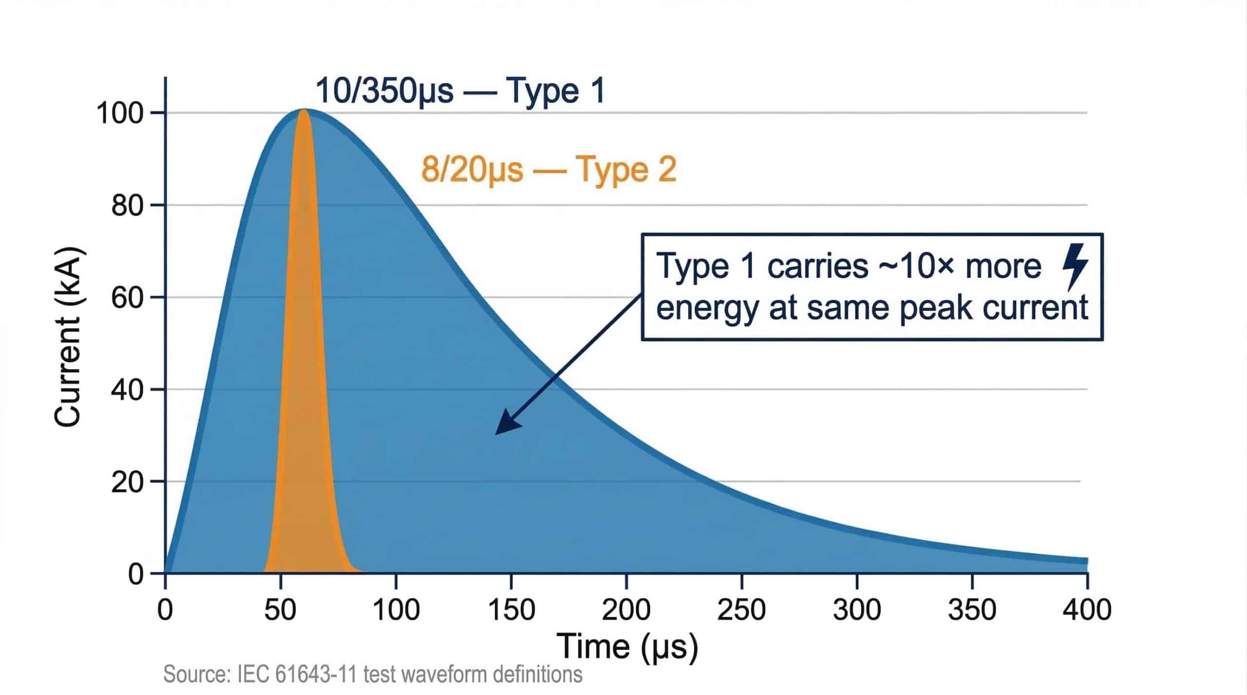
Why this matters for SPD selection: lightning-induced surges (10/350 µs waveform) carry approximately 10× more energy than equivalent switching transients (8/20 µs waveform) at the same peak current. This is precisely why IEC 61643-11 classifies SPDs into different types based on which waveform they are tested against — and why a Type 2 SPD cannot substitute for a Type 1 at the service entrance.
3. How Does a Surge Protection Device Work? Step-by-Step
The working principle of an MOV surge protector follows a four-phase sequence that occurs in microseconds. Understanding each phase clarifies why installation details — particularly lead length and grounding — are as important as the device specifications themselves.
3.1 Phase 1: Normal Operation — High-Resistance Standby
During normal operation, the MOV surge protector is connected in parallel between the line conductor and the protective earth (PE). Its core component — the MOV — presents very high resistance, typically allowing only microamperes of leakage current at normal system voltage (230 V or 400 V). The device is electrically transparent: it draws negligible current and has no effect on the protected circuit.
3.2 Phase 2: Surge Detection — Voltage Threshold Crossing
When a transient overvoltage arrives, the voltage across the SPD begins to rise above normal system voltage. The MOV monitors this continuously. As the voltage crosses the MOV's varistor voltage (reference voltage), the device begins to transition from its high-resistance state. This transition is not a mechanical switch — it is a solid-state quantum effect occurring at grain boundaries within the zinc oxide ceramic, described in detail in Section 4.
3.3 Phase 3: Clamping — Voltage Limiting and Current Diversion
Once conducting, the MOV clamps the voltage across the circuit at the voltage protection level (Up) — typically 1.0–2.5 kV depending on device type and rating. Simultaneously, it diverts the surge current away from the load and redirects it to the grounding conductor and earth electrode. This is the core protective action: the equipment connected downstream never sees the full transient voltage — it sees only Up, which must be lower than the equipment's impulse withstand voltage.
The entire clamping action of the MOV surge protector — from voltage threshold crossing to full conduction — occurs within nanoseconds. As noted in IEEE and experimental research, MOV conduction rises within a few to a few tens of nanoseconds for steep surge fronts, depending on circuit stray inductance.
3.4 Phase 4: Recovery — Return to Standby
Once the transient passes and the voltage falls back below the MOV's varistor voltage, the device returns to its high-resistance state automatically. Power to the protected circuit is never interrupted. The SPD is ready for the next surge event immediately, subject to thermal recovery time for high-energy events.
Lead inductance is a critical installation factor: the clamping action is only effective if the SPD's connecting leads are short and straight. At surge frequencies (~1 MHz), every 1 metre of lead wire adds approximately 1 µH of inductance. During a 20 kA surge: V = L × di/dt = 1 µH × (20 kA / 1 µs) = 20 kV of additional voltage added on top of the SPD's Up. This is why IEC 61643-11 requires total lead length (line terminal to busbar plus PE terminal to ground busbar) not to exceed 0.5 m. A well-specified SPD with 2-metre leads can provide worse protection than a cheaper device installed correctly.
4. How MOV Surge Protectors Work: The ZnO Grain Boundary Mechanism
The Metal Oxide Varistor is the active protection element in the vast majority of industrial and commercial SPDs, and its protective behaviour comes entirely from the microstructure at its zinc oxide grain boundaries. It is a disc-shaped ceramic component whose electrical resistance drops dramatically the moment voltage exceeds its threshold — and that single property is what makes surge protection possible.
4.1 Why the MOV Switches So Fast: ZnO Grain Boundary Mechanism
An MOV is a disc-shaped ceramic component made primarily of zinc oxide (ZnO) particles sintered together with small amounts of bismuth, cobalt, manganese, and other metal oxides. The sintering process creates a microstructure of ZnO grains separated by thin grain boundary layers — and it is these grain boundaries that give the MOV its protective behavior.
Each grain boundary acts as a back-to-back pair of Zener diodes. At voltages below the varistor voltage, these junctions block current flow, keeping the entire MOV in a high-resistance state with leakage below 1 mA. When the applied voltage exceeds the varistor voltage, the grain boundaries go into avalanche — electrons tunnel through the barrier in a process described by the highly nonlinear current-voltage relationship:
I = k · Vα, where α ≫ 1
With α typically ranging from 25 to 70 for industrial-grade MOVs (per IEC 61643-332 / IEEE C62.33), a small increase in voltage above the threshold causes an enormous increase in current. This is the clamping mechanism: the MOV becomes a low-resistance shunt, absorbing surge energy and limiting the residual voltage reaching the load to the clamping voltage (Up).


4.2 Energy Absorption and Thermal Limits
Every surge event deposits energy into the ZnO ceramic as heat. Research cited in IEEE publications shows that disc-type low-voltage MOVs used in MOV surge protectors can handle from a few joules up to several hundred joules per surge, depending on disc diameter and construction. The fundamental limit is thermal runaway: excessive accumulated heat degrades the grain boundary structure, permanently raising the leakage current and eventually causing the thermal disconnector — the SPD's built-in safety mechanism — to open.
This is why MOV quality is non-negotiable for long-term protection reliability. MOV surge protector manufacturers who control the ZnO ceramic formulation — the particle size distribution, bismuth oxide content, and sintering profile — achieve tighter control over the varistor voltage (V1mA) tolerance and energy absorption capability. Assemblers who purchase MOVs from commodity suppliers cannot guarantee this consistency across production batches.
4.3 Parallel MOV Arrays for High Current Ratings
A single MOV disc has a finite current capacity. To achieve the high discharge current ratings required by industrial applications — In = 20 kA, Imax = 40–80 kA — MOV surge protector manufacturers connect multiple MOV discs in parallel. Per IEEE technical literature, n identical MOVs in parallel can theoretically carry approximately n times the surge current at similar clamping voltage. In practice, tolerances in varistor voltage across discs cause unequal current sharing, making tight V1mA matching across the parallel array essential for reliable performance.
This is a critical quality differentiator: an MOV surge protector manufacturer that produces its own MOV chips and performs 100% routine V1mA testing can match parallel arrays precisely. An assembler using commercially sourced MOVs with ±10% V1mA tolerance cannot guarantee equal current sharing — leading to premature failure of the highest-voltage disc in the array during large surge events.
TrilPeak manufactures MOV chips in-house — including the ZnO ceramic production, sintering, and V1mA sorting — ensuring tight varistor voltage tolerance across every parallel array in our SPD products. Combined with 100% routine testing of every finished unit, this vertical integration is the foundation of our discharge current ratings. See our manufacturing process →
5. MOV vs GDT vs TVS: Surge Protection Technologies Compared
MOVs, Gas Discharge Tubes (GDTs), and Transient Voltage Suppressor (TVS) diodes serve distinct, complementary roles in surge protection circuits — and most high-performance industrial MOV surge protectors combine more than one of these technologies. Understanding how each works clarifies when to use which.
| Technology | Working Mechanism | Response Time | Energy Capacity | Primary Application |
|---|---|---|---|---|
| MOV (Metal Oxide Varistor) | ZnO grain boundary avalanche — clamps voltage at varistor threshold | Nanoseconds (ns) | High — hundreds of joules per surge (disc-dependent) | AC power SPDs (Type 1, 2, 3); main energy absorption element |
| GDT (Gas Discharge Tube) | Gas ionization plasma — crowbar switch, latches to arc state at low impedance | Tens to hundreds of ns (gas ionization lag) | Very high current capacity, low energy dissipation (energy diverted to external circuit) | Telecom/signal line SPDs; front-end crowbar in hybrid AC SPDs |
| TVS Diode (Transient Voltage Suppressor) | Zener avalanche — precise clamping voltage, very fast response | Picoseconds (ps) | Low — typically a few joules only | Type 3 point-of-use SPDs; PCB-level protection for electronics |
5.1 Why GDTs and MOVs Are Combined in High-Performance SPDs
A GDT alone acts as a crowbar — once it fires, it holds the voltage near its arc voltage (typically 10–50 V) until the current falls below its holding threshold. This is problematic on AC power lines because the arc can sustain itself through the normal mains cycle. An MOV alone has slower activation than a TVS diode and degrades with each surge event.
The optimal solution for high-performance industrial applications combines both: the GDT handles the first, highest-energy portion of the surge by crowbarring the line, while the MOV element provides precise voltage clamping and absorbs the remaining surge energy. IEEE coordination studies confirm that correctly designed hybrid SPDs achieve lower Up values (better equipment protection) and longer service life than single-technology devices of equivalent current rating.
6. Surge Protector Clamping Voltage (Up): What 330V Means and Why It Matters
Clamping voltage — formally called the voltage protection level (Up) in IEC 61643-11 — is the most important specification for any MOV surge protector, and lower clamping voltage means better equipment protection. But the relationship between Up and system design is more nuanced than simply choosing the lowest available value.
6.1 How Up Is Measured
Up is measured during the standardized discharge current test (In for Type 2, Iimp for Type 1) and represents the peak residual voltage at the SPD's terminals. For a Type 2 SPD with In = 20 kA and Up = 1.5 kV, the device guarantees that a 20 kA surge (8/20 µs) will not cause more than 1.5 kV to appear at the SPD terminals — provided the installation lead length is within the 0.5 m limit specified in Section 3.
6.2 Matching Up to Equipment Withstand Voltage
The fundamental selection rule: Up must be lower than the impulse withstand voltage of connected equipment, with an appropriate safety margin.
| Equipment Category (IEC 60664-1) | Typical Impulse Withstand | Required SPD Up | Typical Applications |
|---|---|---|---|
| Category II | 2.5 kV | Up ≤ 2.0 kV | PLCs, VFDs, inverters, computers, office equipment |
| Category III | 4.0 kV | Up ≤ 3.0 kV | Distribution switchgear, industrial control panels, fixed wiring |
| Category IV | 6.0 kV | Up ≤ 4.0 kV | Service entrance equipment, utility metering |
6.3 The 330 V Clamping Voltage Question
In consumer and light commercial markets, "330 V clamping voltage" is frequently cited as a quality metric for MOV surge protector strips. This refers to the voltage protection level at a specified test current — typically 500 A or 3 kA combination wave per UL 1449. A lower clamping voltage means better protection for the electronics connected downstream.
For industrial and commercial IEC-standard installations, the equivalent specification is Up measured at In (typically 3 kA to 20 kA depending on type). Industrial-grade MOV surge protectors are specified with Up values of 1.0–2.5 kV rather than the 330–500 V range common in consumer products, because industrial systems operate at 230 V or 400 V phase-to-neutral — higher nominal voltages that require higher clamping thresholds to avoid false triggering during temporary overvoltage events.
Practical guidance: for Variable Frequency Drives (VFDs), Programmable Logic Controllers (PLCs), solar inverters, and other Category II equipment in industrial installations, specify Up ≤ 1.5 kV at the sub-distribution board (Type 2 SPD) for optimal protection and longest equipment life. For service entrance (Type 1), Up ≤ 2.5 kV is acceptable because the Type 2 downstream provides the final clamping to equipment-safe levels.
7. Type 1, Type 2, Type 3 SPD: How Multi-Stage Surge Protection Works
A single MOV surge protector at the service entrance is not sufficient to protect an entire industrial facility, because surges enter at multiple points, internal switching creates new transients downstream, and voltage can re-escalate along long cable runs after initial clamping. IEC 61643-11 addresses this through a cascaded protection architecture — Type 1, Type 2, and Type 3 MOV surge protectors installed at successive points in the distribution system, each handling a defined share of the surge energy and progressively reducing the residual voltage reaching equipment.
7.1 Type 1 SPD — Service Entrance Protection
Type 1 SPDs are installed at the main distribution board (service entrance) and are characterized by their Iimp rating — the impulse current tested with the high-energy 10/350 µs waveform that simulates direct or very close lightning effects. A typical industrial Type 1 SPD carries Iimp = 25 kA per pole. The 10/350 µs waveform delivers approximately 10× more energy than an 8/20 µs waveform at the same peak current, which is why Type 1 devices are physically larger and more expensive than Type 2.
7.2 Type 2 SPD — Distribution Board Protection
The Type 2 MOV surge protector is the most widely deployed SPD type in industrial and commercial installations. Characterized by the In (nominal discharge current) rating at 8/20 µs, these devices handle the residual surges that pass through the Type 1 stage plus all internally generated switching transients. In = 10–20 kA is standard for industrial sub-distribution boards. For a complete comparison of all three types, see TrilPeak's Type 1 vs Type 2 vs Type 3 SPD guide.
7.3 Type 3 SPD — Point-of-Use Protection
Type 3 devices are installed within 5 metres of sensitive equipment and provide final-stage clamping to Up ≤ 1.0–1.5 kV. They are optional in most standard industrial installations but become necessary when sensitive equipment (medical devices, precision instruments, data center servers) is located more than 15 m from the nearest Type 2 SPD, because voltage can re-escalate along the cable run between stages.
7.4 The 10-Metre Coordination Rule
The physics of cascaded protection require a minimum cable distance between SPD stages. Per IEC 61643-11 practice, this is typically 10 m between Type 1 and Type 2. The cable inductance between stages (~10 µH for 10 m) creates an impedance that delays voltage escalation at the downstream SPD, allowing the upstream Type 1 to absorb the initial high-energy portion before the Type 2 activates. Without this separation, the faster Type 2 conducts first and absorbs energy it was not designed to handle, causing premature failure.
When physical space prevents 10 m separation — common in compact industrial panels — a decoupling inductor (10–20 µH) installed between stages provides the equivalent impedance artificially. Alternatively, a Type 1+2 combined SPD eliminates the coordination distance requirement entirely by integrating both protection stages in a single tested device.
For the complete selection and installation specification per IEC 61643-11 — including Uc selection, grounding conductor sizing, and backup protection requirements — see TrilPeak's IEC 61643-11 SPD standards guide.
| SPD Type | Test Waveform | Key Rating | Installation Location | Typical Up |
|---|---|---|---|---|
| Type 1 | 10/350 µs | Iimp = 25–100 kA | Service entrance / main distribution board | ≤ 2.5 kV |
| Type 1+2 | 10/350 µs + 8/20 µs (both) | Iimp = 12.5–25 kA + In = 15–20 kA | Service entrance — replaces separate Type 1 + Type 2 | ≤ 2.0 kV |
| Type 2 | 8/20 µs | In = 10–20 kA, Imax = 40–80 kA | Sub-distribution boards throughout facility | ≤ 1.5 kV |
| Type 3 | Combination wave | In = 3–5 kA | Within 5 m of sensitive equipment | ≤ 1.0 kV |
8. Surge Protection Device Working Principle in Practice: Industry Applications
The MOV surge protector clamping mechanism is the same regardless of application — but what changes between industries is the surge environment, the equipment at risk, and the financial consequence of getting the specification wrong. Here is what that means in practice for the most common applications.
Solar PV systems present the most commonly misunderstood surge protection requirement. Because the inverter electrically isolates the DC array side from the AC grid side, an AC MOV surge protector at the grid connection provides zero protection for the inverter's DC input stage — the component most vulnerable to lightning coupling into long array cable runs. The correct approach requires a DC-rated SPD (IEC 61643-31, Uc ≥ 1.2 × Voc(max)) on the array side and a separate AC SPD (IEC 61643-11, Up ≤ 1.5 kV) on the inverter output. A single unprotected lightning event can destroy a $30,000–$50,000 inverter. See TrilPeak's complete solar surge protection guide for DC and AC SPD specification by system size.
Industrial automation and Programmable Logic Controller (PLC) systems face a different problem: internal surge generation. Every time a motor contactor opens, a welding machine fires, or a large Variable Frequency Drive (VFD) starts, the inductive kickback creates a 1–3 kV spike on the same supply rail feeding the PLC and Human-Machine Interface (HMI). A Type 2 MOV surge protector with In ≥ 10 kA and Up ≤ 1.5 kV on the control panel power supply, combined with signal SPDs on all RS485 and fieldbus communication lines, is the minimum protection baseline for any PLC-controlled system. A single corrupted PLC program or damaged I/O card from an unprotected surge can cost far more than the entire SPD installation. See TrilPeak's PLC surge protection guide for wiring diagrams and signal SPD selection.
Data centers and telecom facilities have the tightest Up requirements of any application, because server Power Supply Units (PSUs) and network switches are Category II equipment with only 1.5–2.5 kV impulse withstand. A Type 1+2 MOV surge protector at the main switchboard, Type 2 (Up ≤ 1.5 kV) at every Power Distribution Unit (PDU), and IEC 61643-21 signal SPDs on all copper Ethernet runs is the standard architecture. The overlooked entry point in most data center SPD designs is the Ethernet port: a surge entering through an unprotected copper network cable bypasses every upstream power SPD and destroys Network Interface Cards (NICs) and management controllers directly. See TrilPeak's data center surge protection guide for the full zone-by-zone specification.
HVAC and commercial buildings deal with both external lightning exposure (rooftop equipment, outdoor condensers) and continuous internal switching from compressor contactors and fan motors. The practical consequence is accelerated MOV aging — which means the MOV surge protector on any HVAC panel in a high-cycling environment should be specified with higher Imax ratings (≥ 40 kA) and inspected more frequently than SPDs on less active circuits. For rooftop and outdoor installations, IP65 enclosure rating is mandatory. See TrilPeak's HVAC surge protector guide for equipment-specific recommendations.
9. How to Evaluate SPD Quality: What TrilPeak's Engineers Check Before Shipment
The working principle of an MOV surge protector is straightforward, but the difference between a device that performs as specified over its service life and one that fails silently after the first significant surge event comes down to manufacturing quality. These are the four checkpoints that matter.
9.1 MOV Manufacturing: Vertical Integration vs. Component Assembly
The V1mA (varistor voltage at 1 mA) of the MOV disc determines the precision of the clamping action and the consistency of current sharing in parallel arrays. Manufacturers who produce their own MOV ceramic — controlling ZnO formulation, sintering temperature, and post-sintering sorting — achieve ±5% or tighter V1mA tolerance. Assemblers who purchase commodity MOVs from open market suppliers typically accept ±10–15% tolerance, which translates directly to unequal current sharing and premature failure of the hottest disc in a parallel array during high-energy events.
9.2 Routine Testing: 100% vs. Sampling
IEC 61643-11 requires type testing (full surge performance verification on representative samples) but allows routine testing (production quality verification) to be conducted on a sampling basis. Premium manufacturers test every finished SPD unit for V1mA, leakage current, and continuity before shipment — this eliminates dead-on-arrival units and ensures that the device installed in your panel has been individually verified. Budget manufacturers test batch samples only, which allows defective units to reach the field undetected.
9.3 Certification: Accredited Lab vs. Self-Declared Compliance
IEC 61643-11 certification from an accredited laboratory bearing International Laboratory Accreditation Cooperation (ILAC)-recognized marks such as CNAS, A2LA, TÜV, or VDE means the device has been independently tested to the full standard. The phrase "compliant with IEC 61643-11" in a datasheet without a traceable test report number is self-declared and unverifiable. For project procurement, always request the type test report with the laboratory's accreditation certificate.
9.4 Failure Mode: Safe Disconnection vs. Catastrophic Failure
Every MOV eventually reaches end of life through accumulated surge events. A properly designed SPD incorporates a thermal disconnector — a fusible element within the MOV assembly — that opens safely when the MOV's leakage current rises to a dangerous level, triggering the status indicator and removing the failed MOV from circuit. A poorly designed SPD can fail in short-circuit mode, causing a sustained fault current that requires the backup fuse or MCB to clear, and in the worst case, causing a panel fire if backup protection is absent or undersized.
To understand the warning signs that an SPD is approaching end of life, see TrilPeak's guide on when to replace a surge protector.
10. Frequently Asked Questions About How Surge Protection Devices Work
10.1 How does a surge protector actually work inside — what is the MOV doing?
Inside a surge protector, one or more Metal Oxide Varistor (MOV) discs are connected in parallel between the line conductor and protective earth. At normal system voltage, the MOV's zinc oxide grain boundaries block current flow — the device is electrically invisible. When a surge arrives and the voltage exceeds the MOV's varistor voltage threshold, the grain boundaries enter avalanche conduction within nanoseconds. The MOV's resistance drops from megaohms to a few ohms, clamping the voltage at the protection level (Up) and diverting the surge current to ground. Once the transient passes, the MOV recovers to its high-resistance state automatically — solid-state, no moving parts, no power interruption to the load.
10.2 What is an MOV surge protector and how long does it last?
An MOV surge protector uses Metal Oxide Varistor discs as its active protection element. Each time the MOV absorbs a surge event, the zinc oxide ceramic degrades slightly — the grain boundaries crack microscopically and the varistor voltage shifts. With each event, the MOV's leakage current increases incrementally. For industrial-grade MOV surge protectors in typical environments, service life ranges from 10 to 15 years under moderate surge activity. In high lightning exposure areas or locations with frequent switching transients, this can drop to 5–8 years. The MOV's built-in thermal disconnector opens when degradation reaches a dangerous level, triggering the red status indicator, at which point the unit must be replaced immediately.
10.3 What does 330V clamping voltage mean on a surge protector, and is lower always better?
A 330V clamping voltage surge protector limits the peak voltage reaching connected equipment to 330 V during a standardized surge test. Lower clamping voltage means better protection because less overvoltage stress reaches equipment. In IEC 61643-11 terminology, this is called the voltage protection level (Up). Industrial SPDs are typically specified with Up = 1.0–2.5 kV because they operate on 230 V or 400 V systems — the higher nominal voltage requires a higher clamping threshold to avoid false triggering during temporary overvoltages. So "lower is better" holds true within a given voltage class, but comparing a 330V consumer strip against a 1.5 kV industrial SPD is not a valid quality comparison — they serve different voltage environments entirely.
10.4 What is the difference between a Type 1, Type 2, and Type 3 surge protection device?
The three types differ in where they are installed and what surge waveform they are tested against. A Type 1 surge protection device is installed at the service entrance and must survive the 10/350 µs waveform that simulates partial lightning current — the most energy-intensive surge type. Type 2 SPDs are installed at distribution boards and handle the 8/20 µs waveform representing switching transients and residual lightning surges. Type 3 SPDs are point-of-use devices installed within 5 m of sensitive equipment, providing final-stage clamping. Using a Type 2 at the service entrance where a Type 1 is required is a common and dangerous specification error — the Type 2 will fail catastrophically on a direct lightning event.
10.5 What is the difference between an MOV surge protector and a non-MOV (series mode) surge protector?
MOV surge protectors use Metal Oxide Varistor discs as the clamping element — they degrade slightly with each event but offer the best combination of energy handling, response speed, and DIN-rail form factor for industrial IEC 61643-11 applications. Non-MOV surge protectors (series mode or filter-based) use inductors and capacitors to filter surges and do not degrade, but they are significantly larger, heavier, and more expensive, and struggle with very fast, very high current surges. For industrial procurement, MOV-based SPDs also have a practical field advantage: the built-in status LED tells you immediately when protection has been lost. Non-MOV devices typically provide no equivalent end-of-life indication.
10.6 How does a whole house surge protector work differently from a plug-in power strip?
A whole house surge protector (service entrance SPD) is installed at the main distribution board and intercepts surges before they enter the building's wiring — it uses Type 1 or Type 2 rated MOV arrays capable of handling 10–100 kA discharge current. A plug-in surge protector strip (Type 3) is installed at the outlet level and provides only the final protection layer for residual surges. Using a plug-in strip without a service entrance SPD means all the lightning energy that enters through the utility connection travels through the building's wiring before reaching the strip, which will almost certainly be overwhelmed. The correct architecture is always service entrance protection first, with point-of-use strips as supplementary protection — the cascaded Type 1 → Type 2 → Type 3 architecture defined in IEC 61643-11.
10.7 Can I test whether my MOV surge protector still works?
Visual inspection of the status indicator (green = operational, red = failed) is the primary field test for installed SPDs. Red means the thermal disconnector has opened and the unit must be replaced immediately — the circuit is no longer protected. For more detailed verification, a qualified electrician can perform insulation resistance testing between L-PE with the SPD disconnected — a significant drop from the original measurement indicates MOV degradation. Full surge performance verification requires specialized surge testing equipment not practical for field use. TrilPeak recommends preventive replacement every 10 years regardless of indicator status, and immediate replacement after any nearby direct lightning strike. See TrilPeak's when to replace a surge protector guide for a complete inspection checklist.
10.8 How does surge protection work for solar PV systems — do I need both AC and DC SPDs?
Yes — solar PV surge protection requires SPDs on both the DC side and the AC side of the inverter. The inverter electrically isolates these two circuits, so an AC SPD at the grid connection provides zero protection for the inverter's DC input stage. On the DC side, a DC-rated SPD per IEC 61643-31 is required, rated at Uc ≥ 1.2 × Voc(max) of the array. On the AC side, a standard AC SPD per IEC 61643-11 handles grid switching transients and utility surges. Never install an AC SPD on the DC side — AC SPDs cannot quench DC arcs and will fail destructively. See TrilPeak's complete solar surge protection guide for specification by system size.
10.9 What is the surge protection device working principle for industrial automation and PLC systems?
The surge protection device working principle in industrial systems follows the same MOV clamping mechanism, but the specification demands are higher. Industrial environments generate frequent switching transients from motors, VFDs, welding equipment, and contactors, in addition to external lightning surges. This means industrial SPDs need higher Imax ratings (40–80 kA) to survive repeated transients over their service life, lower Up values (≤ 1.5 kV) to protect Category II equipment like PLCs and inverters, and IEC 61643-11 Type 2 certification with accredited lab documentation for project approval. Signal SPDs on all RS485 and fieldbus communication lines are equally critical, since a surge that bypasses the power SPD and enters through the communication port can destroy PLC I/O cards directly.
11. Conclusion: What This Means for Your SPD Specification
The surge protection device working principle is straightforward physics. What is not straightforward is finding a supplier whose manufacturing can back it up. The MOV surge protector clamping mechanism only delivers its rated performance when the zinc oxide grain boundaries are produced to consistent tolerance, when the parallel array is matched within ±5% V1mA, and when every unit has been individually tested before it leaves the factory. A datasheet claiming "40 kA Imax, IEC 61643-11 compliant" means nothing without a traceable accredited lab test report behind it.
The practical checklist for your next project: specify Up relative to the equipment's impulse withstand voltage; keep installation leads under 0.5 m; use cascaded Type 1+2 and Type 2 MOV surge protectors rather than a single device; and demand the type test certificate, not just the compliance claim. TrilPeak manufactures MOV surge protectors from chip to finished product — ZnO ceramic, sintering, disc sorting, assembly, and 100% routine testing all under one roof — and provides application-specific SPD selection and IEC 61643-11:2025 type test documentation for every project.
Related Resources & Standards
Specifying SPDs for an industrial, solar, or commercial project?
TrilPeak manufactures MOV surge protectors from chip to finished product, with engineers responding within 24 hours with application-specific selection support and IEC 61643-11:2025 test documentation. CE certified · IEC 61643-11 · engineering reply within 24h.