
PLC Surge Protection: 3-Layer Engineering Guide
Quick Answer
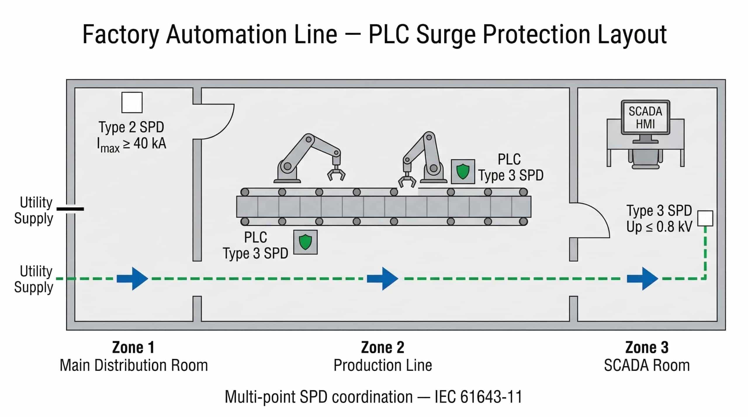
PLC surge protection is the installation of coordinated Surge Protective Devices (SPDs) at three points in a PLC-based control system: an IEC 61643-11 Type 2 SPD at the incoming AC feed of the control cabinet, a DC SPD directly across the internal 24VDC control bus, and signal line SPDs (per IEC 61643-21) at every field cable entry point.
PLCs are Category I–II equipment with impulse withstand voltage (Uw) of only 0.8–1.5 kV per IEC 60364-4-44—meaning a single unmitigated transient from a VFD, nearby motor start, or utility switching event can destroy CPU modules, I/O cards, and communication interfaces simultaneously. Hardware investment: $50–$300 per cabinet. Single unprotected surge event cost: $15,000–$50,000 in hardware and downtime.
- Layer 1: Type 2 AC SPD at cabinet incoming feed (IEC 61643-11)
- Layer 2: DC SPD across 24VDC control bus (IEC 61643-31), Up ≤ 50V
- Layer 3: Signal line SPDs at every field cable entry (IEC 61643-21)

Replacing a CompactLogix CPU costs $2,000–$10,000 in hardware. The real cost is the 48-hour production shutdown—sourcing a replacement module, reloading firmware, restoring the logic program from backup, and re-terminating I/O wiring before the line runs again.
In most documented PLC failures from surge events, hardware replacement represents less than 20% of total incident cost; the remainder is downtime. And in the majority of those cases, the surge did not come from lightning. It came from the VFD in the adjacent cabinet switching a motor load—generating high-frequency transients that coupled onto the shared 24VDC bus and destroyed the I/O modules that the maintenance team had assumed were protected.
Effective PLC surge protection requires more than a single device at the main panel. It requires a coordinated 3-layer cascade addressing every electrical path into the PLC: AC power, DC control bus, and signal lines. Each path has different energy levels and different vulnerable endpoints—which is why surge protection for PLC systems cannot be solved with a single panel-mounted device.
Why PLCs Are the Most Surge-Vulnerable Equipment in Your Facility
Modern PLCs execute logic at 3.3V or 5V internally. Their discrete I/O modules interface with the factory floor at 24VDC—but the surge withstand rating of those I/O circuits is surprisingly low. Per IEC 61000-4-5 testing, most industrial PLC I/O modules carry Level 2 immunity: 500V line-to-line surge withstand. Analog 4-20mA modules and RS-485 communication ports are similarly rated at Level 2–Level 3 (500V–1kV). The CPU logic board itself has no meaningful surge withstand—it relies entirely on the power supply and I/O module protection upstream.
EPRI's destructive surge testing on PLCs paired with adjustable speed drives applied surges up to 6kV peak. PLCs survived to 3–6kV before reaching performance criterion C (temporary malfunction) or D (damage requiring repair)—but this test was performed with factory-standard power supply protection only. In field installations, that protection is frequently absent or insufficient on the DC bus and signal paths.
| PLC Circuit | Operating Voltage | IEC 61000-4-5 Level | Max Surge Withstand |
|---|---|---|---|
| CPU internal logic | 3.3V / 5V DC | Not rated (internal) | < 50V |
| Discrete 24VDC I/O modules | 24V DC | Level 2 | 500V line-to-line |
| Analog 4-20mA input modules | 24V DC | Level 2 | 500V line-to-line |
| RS-485 / Profibus comms | 5V DC differential | Level 2 | 500V–1kV |
| 120/230V AC power supply input | 120V / 230V AC | Level 3 | 1.5kV line-to-neutral |
| Industrial Ethernet port | 5V PHY logic | Level 3 | ±2kV (IEC 61000-4-5) |
Rockwell Automation's Bulletin 4983 application note confirms that surges cause both immediate catastrophic failure and latent effects—random memory latching or erasure that produces unexplained intermittent faults weeks after the surge event. This latent damage is the hardest to diagnose and the most common cause of "unexplained" PLC reliability problems in VFD-heavy environments.
The 3 surge entry paths into a PLC:
The AC power supply input is the most obvious path and the most commonly protected. What engineers routinely miss are the other two: the 24VDC control bus—a direct distribution spine to every I/O card and sensor in the cabinet—and the field I/O cables entering from outside the cabinet.
A field cable running 50 meters to an outdoor sensor acts as an antenna. A nearby lightning strike couples energy onto that cable inductively, and it delivers that surge directly to the PLC I/O terminal—bypassing every SPD installed at the main panel or cabinet AC feed entirely. This is the back-door vulnerability. Protecting the AC input while leaving signal lines unprotected is the most common and costly installation error in PLC surge protection practice.
The 3 Layers of PLC Surge Protection
A single SPD at the main panel reduces an incoming 10kV transient to roughly 2.5–4kV. That residual voltage travels down the cable to the PLC cabinet, where it encounters equipment rated for 0.8–1.5kV impulse withstand. The gap between what the panel SPD delivers and what the PLC can survive is what the 3-layer cascade bridges. For a facility-wide overview of the upstream protection hierarchy, see our power panel surge protection guide.
Layer 1 — AC Power Supply Protection
A Type 2 DIN-rail SPD installed on the incoming AC terminal block of the PLC cabinet, positioned between the cabinet MCB and the 24VDC power supply unit. This device intercepts grid transients and residual energy passed through by the upstream panel SPD.
Required parameters for a 230V AC control cabinet feed:
- Imax ≥ 40 kA (8/20 µs) — handles repetitive switching transients and residual lightning energy
- Up ≤ 1.5 kV — IEC 60364-4-44 permits up to 2.5 kV for Category II, but PLC power supplies need tighter clamping to protect their internal filter capacitors
- Uc ≥ 275V AC — correct for TN systems at 230V; for 480V US systems, Uc ≥ 530V
- SCCR must match the prospective fault current at the cabinet feed point
For backup fuse sizing and MCB coordination at this level, refer to our circuit breaker vs surge protector coordination guide.
Layer 2 — 24VDC Control Bus Protection
The 24VDC bus is the distribution spine connecting the PLC CPU to every I/O module, sensor, and actuator in the cabinet. A single unmitigated transient on this bus destroys all connected I/O cards simultaneously—not just the one nearest the entry point. This layer is the most frequently omitted in practice, and the most consequential when missing.
A DC surge protector wired in parallel directly across the 24VDC bus inside the cabinet:
- Uc ≥ 30V DC — must remain inactive during normal 24V operation with typical ±10% voltage tolerance
- Up ≤ 50V — must clamp below the 500V surge withstand of I/O modules, with significant margin
- Response time < 25 ns — critical for fast VFD switching transients, which have rise times in the nanosecond range
- IEC 61643-11 or IEC 61643-31 classification depending on DC topology
The Up ≤ 50V target is not arbitrary: IEC 60364-4-44 Category I equipment (PLC internal circuits) has Uw = 0.8 kV at system voltage, but the practical withstand of 24V logic circuits is far lower. The 50V clamping target provides substantial margin against the 500V Level 2 I/O withstand and complete protection for 5V internal logic.
Layer 3 — Signal Line and Field Cable Protection
Every copper cable entering the PLC cabinet from outside is a potential surge entry path—and the most overlooked aspect of surge protection for PLC installations. Whether from a field instrument 5 meters away or a remote sensor 200 meters away, each cable bypasses all upstream protection. IEC 62305-4 identifies cables crossing LPZ boundaries and cables longer than 10m between buildings as requiring SPD protection at the entry point. The SPD must be installed at the terminal block row where the cable enters the cabinet, not adjacent to the PLC module itself—installing it at the module end allows the cable to act as a radiating antenna inside the cabinet before the energy is diverted.

Required SPD parameters by signal type:
| Signal / Interface | IEC Standard | Uc | Max Up | Min In | Notes |
|---|---|---|---|---|---|
| 4-20mA analog input | IEC 61643-21 | 33V DC | ≤ 50V | ≥ 5 kA | Low capacitance to preserve loop accuracy |
| 24VDC digital I/O | IEC 61643-21 | 30V DC | ≤ 60V | ≥ 10 kA | Matches I/O module withstand |
| RS-485 / Modbus RTU | IEC 61643-21 | 5–7V DC | ≤ 15V | ≥ 5 kA | Balanced differential pair protection |
| Profibus DP | IEC 61643-21 | 5–7V DC | ≤ 20V | ≥ 5 kA | 9-pin D-sub or terminal block format |
| Ethernet / Profinet / EtherNet/IP | IEC 61643-21 | 48V (PoE) | ≤ 50V | ≥ 2.5 kA | Insertion loss < 1 dB at 100 MHz |
The Ethernet SPD parameter that most engineers underestimate is the clamping voltage. The PHY chip on a PLC's Ethernet port operates at 5V logic. A device that clamps at 150V is technically passing the IEC 61000-4-5 test but is still destroying the PHY transceiver—which fails silently before the CPU or I/O shows any fault code. The 50V maximum clamping voltage target is derived from the actual silicon withstand of Ethernet PHY components, not from the test standard.
Full Cascade: From Main Panel to PLC
| Protection Stage | SPD Type | Location | Residual Up Passed Downstream | Cable Sep. |
|---|---|---|---|---|
| Main service entrance | Type 1+2 | Main MDB | ≤ 4 kV | — |
| MCC / sub-panel | Type 2 | MCC incoming | ≤ 2.5 kV | ≥ 10 m from above |
| PLC cabinet AC feed | Type 2 | Cabinet DIN rail | ≤ 1.5 kV | ≥ 10 m from above |
| 24VDC bus | DC SPD | Inside cabinet | ≤ 50V | Parallel to bus |
| Signal / field cables | Signal SPD (IEC 61643-21) | Cabinet cable entry | ≤ 5–50V (by type) | At terminal row |
IEC 62305-4 Clause 6.2.4 requires minimum 10 meters of cable separation between cascaded SPD stages for inductive decoupling. Where the panel and PLC cabinet are closer than 10m, a decoupling inductor must be inserted in series between stages. Without this separation, the downstream SPD fires before the upstream one—defeating the energy-sharing principle of the cascade. This is covered in detail in our Type 1 vs Type 2 vs Type 3 SPD comparison guide.
IEC Standards for PLC Surge Protection
Four standards govern PLC surge protection practice. Understanding how they interact prevents the most common specification errors.
- IEC 61000-4-5 defines what the PLC can withstand without any SPD—the baseline immunity test. Level 2 = 500V / 0.25kA; Level 3 = 1kV / 0.5kA; Level 4 = 2kV / 1kA. This is the starting point for SPD selection: the SPD's Up must be below the PLC's IEC 61000-4-5 rating, with margin.
- IEC 60364-4-44 defines Overvoltage Categories for installation locations. PLC cabinets are Category II (Uw = 2.5kV for 230/400V systems). PLC internal circuits and 24V control circuits are Category I (Uw = 1.5kV or 0.8kV). The SPD Up at each stage must be below the Uw of the equipment it protects.
- IEC 61643-11 governs the SPD hardware itself—the Type 2 and Type 3 devices used at each layer of PLC surge protection for power line applications. For a complete breakdown of test waveforms and parameter definitions, see our IEC 61643-11 standards guide.
- IEC 61643-21 / IEC 61643-22 govern signal and data line SPDs—the standard specifically applicable to 4-20mA, RS-485, Profibus, and Ethernet protectors used in Layer 3 PLC protection.
- IEC 62305-4 governs SPD application within Lightning Protection Zones—determines when field cables require SPD protection based on cable length, routing (underground vs overhead), and LPZ boundary crossings.
PLC Surge Protection by Application
Manufacturing Plants with VFDs
In manufacturing environments, correct PLC surge protection must address internal threats before external ones. The dominant threat is not lightning—it is VFD switching transients. Every motor start and stop generates high dv/dt transients that couple onto the 24VDC bus and adjacent I/O cables through capacitive and inductive paths. A PLC cabinet physically sharing a backpanel or cabinet enclosure with a VFD is under continuous low-level surge stress, incrementally degrading I/O module capacitors and transceiver circuits before catastrophic failure occurs.
The critical installation rule for control panel surge protection in VFD environments: the PLC cabinet PE connection must never share the same earth point as the VFD cabinet without proper high-frequency separation. VFD earth currents elevate the ground potential reference of the PLC's zero-volt bus, corrupting I/O signals and accelerating MOV degradation in any installed SPDs. Layer 1 + Layer 2 is the minimum—the DC bus SPD is not optional when VFDs are present.
VFD surge protection at the VFD output is a separate but complementary measure—motor cable dV/dt filters protect the motor winding insulation and reduce the magnitude of the transients that couple back onto the 24V bus. Both measures are required in high-drive-count automation systems.
Oil & Gas and Hazardous Area PLCs
Facilities in petrochemical processing and offshore environments require PLC surge protection for long field cable runs—sometimes hundreds of meters—in high lightning exposure zones. The key misunderstanding in these installations is the assumption that Zener barriers provide complete surge protection for Ex-zone circuits. Zener barriers limit energy to prevent ignition in the hazardous area, but they do not divert high-energy surge current—they absorb it, often exceeding their ratings. Non-IS analog inputs and the input side of the barriers themselves require dedicated IEC 61643-21 compliant signal SPDs rated for the specific Uc and Up of the circuit.
Outdoor PLC cabinets and junction boxes in these environments require IP54 minimum (IP65 for direct weather exposure), with SPDs rated for the ambient temperature range and humidity levels of the installation site.
Remote RTUs and Outdoor PLCs
Remote terminal units in pipeline telemetry, water/wastewater lift stations, and substation automation have no upstream SPD cascade—the RTU is the first and only protection point. PLC surge protection for remote RTUs requires a completely different approach: the RTU or outdoor PLC must be treated as its own protection zone, requiring Type 1+2 on the AC feed (if overhead supply), all signal line SPDs at cable entry, and a dedicated coaxial surge protector inline with any external antenna feed for cellular or radio WAN connections.
Substation RTUs following IEC 61850 require surge withstand per IEEE C37.90.1 (1–5kV surge withstand capability)—which defines the immunity target for the SPD Up at the serial and Ethernet ports of the RTU.
Ethernet, Profinet, and EtherNet/IP Networks
Industrial Ethernet cables between buildings are the fastest-growing PLC surge vulnerability in modern manufacturing. A CAT6 cable running between two building distribution panels—even one that is properly shielded—can couple thousands of volts of induced surge energy during a nearby lightning event. IEC 62305-4 requires SPD protection on Ethernet cables crossing LPZ boundaries (building to building) or exceeding 10m in exposed routing.
Selection criteria for an Ethernet surge protector in PLC applications: insertion loss < 1 dB at 100 MHz (to avoid degrading gigabit throughput), PoE support if required (Uc ≥ 48V for PoE+), and Up ≤ 50V for PHY chip protection. Rockwell Stratix switches and Siemens SCALANCE series both specify IEC 61000-4-5 Level 3 (±2kV) immunity—meaning the Ethernet SPD must clamp below 2kV for the switch port to survive, and below 50V for the PHY silicon to remain undamaged long-term.
Managed switches in PLC Ethernet networks require the same protection as the PLC itself—a network surge protector at each switch port prevents the entire segment from failing when one cable takes a hit. A surge that destroys the switch takes down the entire network segment, with the same production impact as destroying the PLC CPU directly. For detailed RJ45 SPD selection, see our Ethernet surge protector guide.
Complete SPD Specification Matrix for PLC Cabinets
| Protection Point | IEC Type | Min Uc | Max Up | Min Imax | Standard |
|---|---|---|---|---|---|
| 230V AC cabinet feed | Type 2 | 275V AC | ≤ 1.5 kV | ≥ 40 kA | IEC 61643-11 |
| 480V AC cabinet feed (US) | Type 2 | 550V AC | ≤ 2.5 kV | ≥ 40 kA | IEC 61643-11 |
| 24VDC control bus | DC SPD / Type 3 | 30V DC | ≤ 50V | ≥ 10 kA | IEC 61643-11/-31 |
| 4-20mA analog input | Signal SPD | 33V DC | ≤ 50V | ≥ 5 kA | IEC 61643-21 |
| 24VDC digital I/O line | Signal SPD | 30V DC | ≤ 60V | ≥ 10 kA | IEC 61643-21 |
| RS-485 / Modbus RTU | Differential SPD | 5–7V DC | ≤ 15V | ≥ 5 kA | IEC 61643-21 |
| Profibus DP | Differential SPD | 5–7V DC | ≤ 20V | ≥ 5 kA | IEC 61643-21 |
| Ethernet / Profinet / EtherNet/IP | High-freq SPD | 48V DC (PoE) | ≤ 50V | ≥ 2.5 kA | IEC 61643-21 |
| Coaxial / antenna (RTU/cellular) | Coaxial SPD | per frequency | ≤ 50V | ≥ 5 kA | IEC 61643-21 |
This matrix is the core engineering reference for PLC surge protection specification. Every row corresponds to one physical installation point in a fully protected cabinet. For each interface type, the parameters are derived from IEC 61000-4-5 immunity levels and IEC 60364-4-44 overvoltage categories—the two standards that define what the PLC can survive and therefore what the upstream SPD must achieve.
Installation Rules for PLC Surge Protection
Correct installation is as important as correct specification. The most common finding in failed PLC surge protection installations is not wrong product selection—it is lead length violation or incorrect grounding, both of which are entirely avoidable.
The 0.5m maximum total lead length rule (L1 + L2, from busbar to SPD to PE bar) applies at the cabinet level exactly as it does at the main panel. Each meter of connecting wire adds approximately 1µH inductance—at a surge rise rate of 10kA/µs, that adds 1,000V of inductive voltage drop directly to the SPD's Up. A Type 2 SPD rated Up = 1.5kV with 1m lead violation effectively delivers 2.5kV to the 24V power supply input—destroying it.
For compact PLC cabinets where 0.5m is geometrically difficult, the U-connection method (CT2 per IEC 60364-5-53 Annex C) routes the main conductor through the SPD terminals, reducing effective branch length to near zero.
Grounding Architecture
All SPDs within a single PLC cabinet must terminate to a single, dedicated low-impedance PE busbar—not daisy-chained between devices. Daisy-chaining creates additive impedance that elevates the SPD earth reference during a surge discharge, reducing clamping effectiveness and allowing ground potential to rise inside the cabinet. The PE conductor from each SPD to the cabinet earth bar should be ≥ 6mm² Cu for signal SPDs and ≥ 16mm² Cu for the Layer 1 AC power SPD.
Signal SPD Placement
Signal line SPDs must be installed at the point where the cable enters the cabinet—at the terminal block row, not adjacent to the PLC I/O module. A cable entering the cabinet and running unprotected to the PLC module radiates EMI onto adjacent clean wiring inside the cabinet before reaching the protector. The SPD at the entry point intercepts the surge before it propagates inside the enclosure.
Post-Installation Verification
Before commissioning: verify PE continuity with a calibrated micro-ohmmeter, confirm all SPD status indicators show green, and document the baseline surge counter reading (if equipped) for future maintenance reference. The operational importance of status monitoring and replacement triggers is covered in our when to replace a surge protector guide.
Installation Compliance Checklist
| Step | Verification | Requirement |
|---|---|---|
| 1 | SPD type confirmation | Type 2 at AC feed; DC SPD at 24V bus; Signal SPD at each cable entry |
| 2 | Lead length measurement | Total L1 + L2 ≤ 0.5m per IEC 60364-5-53 Clause 534.4.2.3 |
| 3 | Earth termination | Star-point connection — no daisy-chain; ≥ 6mm² Cu for signal; ≥ 16mm² for AC |
| 4 | Signal SPD position | At terminal block entry row — not at PLC module end |
| 5 | Uc verification | AC SPD Uc ≥ 275V (230V TN) or ≥ 550V (480V); DC SPD Uc ≥ 30V |
| 6 | Up coordination | Layer 1 Up ≤ 1.5kV; Layer 2 Up ≤ 50V; signal SPD Up per matrix above |
| 7 | Cascade separation | ≥ 10m between panel SPD and cabinet SPD; decoupling inductor if < 10m |
| 8 | Status indicator | All modules show green before commissioning |
| 9 | Backup fuse sizing | Per IEC 60364-5-53 Table 2 (Imax ≤ 25kA → 125A gG fuse) |
| 10 | Remote alarm wiring | Alarm contact wired to PLC DI or BMS for end-of-life detection |
Standards and Certifications
| Standard | Scope | PLC Protection Application |
|---|---|---|
| IEC 61000-4-5 | PLC surge immunity testing | Defines what the PLC withstands without SPD — the Up target baseline |
| IEC 60364-4-44 | Overvoltage categories | Category I/II defines Uw for PLC circuits; SPD Up must stay below this |
| IEC 61643-11 | SPD performance (power lines) | Governs Type 2/3 devices at AC feed and DC bus |
| IEC 61643-21/-22 | SPD performance (signal lines) | Governs all signal, data, and communication line SPDs |
| IEC 62305-4 | LPZ application guide | Determines when field cables and Ethernet runs require SPD protection |
| CE Marking | EU/international conformity | Required for B2B export to EU, MEA, and APAC markets |
TrilPeak PLC surge protection devices are IEC 61643-11 certified and CE marked, covering EU, Middle East, Asia-Pacific, and international B2B project requirements. For North American projects referencing NEC Article 285 and UL 1449, note that the IEC risk-based approach and the NEC listing-based approach serve the same protective function with different verification frameworks.
For authoritative standard documentation, the IEC webstore provides IEC 61643-11, IEC 61643-21, and IEC 61000-4-5. Rockwell Automation's Bulletin 4983 application note provides PLC-specific surge protection guidance directly from the manufacturer. IEEE surge withstand standards for RTU and substation applications are available via IEEE Xplore.
Conclusion
Effective PLC surge protection is not a single device—it is a coordinated architecture. Engineers who have implemented PLC surge protection as a single panel-mounted SPD consistently report recurring I/O failures until the DC bus and signal paths are also addressed. Layer 1 at the AC cabinet feed intercepts grid transients. Layer 2 at the 24VDC bus prevents simultaneous destruction of all connected I/O. Layer 3 at signal line entries closes the back-door vulnerability that bypasses all upstream protection. The complete specification matrix above defines the correct parameters at each layer for every interface type commonly found in industrial control panels.
For the upstream panel-level protection that feeds into this cascade, see our power panel surge protection guide. For product selection guidance across Type 1, 2, and 3 SPDs, refer to our industrial surge protector selection guide.
Frequently Asked Questions
PLC surge protection is the coordinated installation of IEC 61643-11 Surge Protective Devices at three points in a PLC control system: a Type 2 SPD at the incoming AC feed of the control cabinet, a DC SPD across the 24VDC internal control bus, and IEC 61643-21 signal line SPDs at every field cable entry point. PLCs are Category I–II equipment with impulse withstand voltage of only 0.8–1.5kV, making them the most surge-vulnerable equipment in a typical industrial facility.
If the PLC cabinet is fed from a distribution panel, shares a building with motors or VFDs, or receives any field cables from outside the cabinet, surge protection is required. Rockwell Automation's Bulletin 4983 explicitly states that approximately 80% of PLC power supply failures are attributable to power quality events including surges and transients—making SPD installation not optional but a baseline reliability requirement for any industrial control system.
Both. A Type 2 SPD (IEC 61643-11) is installed at the incoming AC power terminal of the PLC cabinet. A DC SPD (Type 3 or IEC 61643-31 classified) is installed directly across the 24VDC internal bus. Signal line SPDs certified to IEC 61643-21 are installed at field cable entry points. Each layer addresses a different surge entry path and requires different parameters—they cannot substitute for each other.
Install a DC SPD in parallel directly across the 24VDC bus inside the cabinet, as close as possible to the power supply output terminals. Required parameters: Uc ≥ 30V DC (to stay inactive during normal operation), Up ≤ 50V (to clamp below I/O module surge withstand), and response time < 25 ns. The PE conductor from the SPD to the cabinet earth bar must be ≥ 6mm² Cu, connected to the cabinet star-point PE, not daisy-chained from another device.
Yes—this is the primary real-world failure mechanism for PLCs in manufacturing environments. Every motor start, stop, or speed change generates high dv/dt switching transients from the VFD's IGBT switching. These transients couple onto the shared 24VDC bus and adjacent I/O signal cables through capacitive and inductive paths. Repeated low-level VFD transients cause latent degradation of I/O module capacitors and transceiver circuits, producing intermittent faults and premature failures before any single catastrophic event occurs.
Install IEC 61643-21 compliant signal SPDs at the terminal block row where each field cable enters the cabinet—not adjacent to the PLC module. Each cable type requires a specifically matched SPD: Up ≤ 50V for 4-20mA analog lines, Up ≤ 15V for RS-485/Modbus, and Up ≤ 50V with insertion loss < 1 dB at 100MHz for Ethernet/Profinet. Any field cable longer than 10m or entering from outside the building requires signal line protection regardless of upstream panel SPD installation.
An IEC 61643-21 compliant RJ45 surge protector with: Uc ≥ 48V DC (for PoE applications), Up ≤ 50V (to protect the 5V PHY chip on the Ethernet port), insertion loss < 1 dB at 100 MHz (to maintain gigabit throughput), and support for 10/100/1000 Mbps. The clamping voltage is the critical parameter—devices clamping at 150V will pass IEC 61000-4-5 tests but will still destroy Ethernet PHY transceivers over time. Rockwell Stratix switches and Siemens SCALANCE series both specify Level 3 (±2kV) immunity for their Ethernet ports.
Three reasons. First, even a Type 1+2 panel SPD reduces an incoming transient to 2.5–4kV residual—still far above the 0.8–1.5kV Uw of PLC circuits. Second, every 10m of cable between the panel SPD and the PLC cabinet adds 1–2kV of inductive voltage drop, increasing the residual voltage at the PLC terminals. Third, the panel SPD provides no protection against surges entering through field I/O cables—the back-door path that bypasses all panel-level protection entirely.
Visual inspection of the status indicator at every scheduled maintenance interval—minimum quarterly in manufacturing environments. Immediate inspection after any confirmed surge event (lightning strike, motor fault, utility interruption), even if indicators show green. Latent MOV degradation is not always externally visible. SPDs with surge counters enable data-driven replacement: replace when cumulative surge count exceeds the manufacturer's rated number of events, or when the counter shows a sudden high-magnitude event. Annual PE continuity verification is also recommended.
Surge protection (SPDs) diverts high-energy transient overvoltages to the protective earth conductor—single-event, high-magnitude events lasting microseconds. EMC filtering (line filters, ferrite chokes, common-mode chokes) attenuates continuous high-frequency conducted emissions and radio-frequency interference—lower-energy, repetitive noise present during normal operation. In VFD-heavy environments, both are required. The SPD handles the discrete transient events from motor switching; the EMC filter handles the continuous HF noise floor generated by VFD carrier frequencies. They are complementary, not interchangeable.
The SPD specification is not brand-specific—it is derived from the IEC immunity ratings published in the PLC manufacturer's datasheet. Confirm the IEC 61000-4-5 Level for each port (CPU power, I/O modules, Ethernet, serial). Confirm the IEC Overvoltage Category (Category I or II) for the installation location. Then select SPDs with Up below the Uw of each circuit. For Siemens S7-1500 CPUs (rated ±2kV on supply lines per IEC 61000-4-5) and Rockwell ControlLogix (±2kV line-to-earth on power ports), the Layer 1 Type 2 SPD with Up ≤ 1.5kV provides the required coordination margin.
Related Resources
The following guides and product pages from TrilPeak cover the complete PLC surge protection hierarchy—from main service entrance to cabinet signal lines. External standards references are also listed for specification work.
Related Engineering Guides
- Power Panel Surge Protection: Engineering Guide — upstream panel-level SPD selection and LPZ zone requirements
- Industrial Surge Protector Selection Guide — Type 1/2/3 product selection for industrial facilities
- Type 1 vs Type 2 vs Type 3 SPD: Full Comparison — parameter definitions, test waveforms, and application matrix
- IEC 61643-11 SPD Standards Guide — complete breakdown of test classes, Iimp, Imax, Up, Uc, and TOV requirements
- Ethernet Surge Protector Guide — RJ45 SPD selection for Profinet, EtherNet/IP, and industrial Ethernet
- Circuit Breaker vs Surge Protector Coordination — backup fuse sizing and MCB coordination for SPD installation
- When to Replace a Surge Protector — status indicator interpretation, surge counter use, and replacement criteria
TrilPeak Products for PLC Cabinet Protection
- Type 2 Surge Protector — IEC 61643-11 certified, DIN-rail, for PLC cabinet AC feed (230V / 480V)
- Type 3 Surge Protector — point-of-use device-level protection for PLC and HMI equipment
- DC Surge Protector — 24VDC control bus protection, Up ≤ 50V, Uc ≥ 30V DC
- Network Surge Protector — Ethernet and fieldbus signal line protection for Profinet and EtherNet/IP
- 3-Phase Surge Protector — for three-phase industrial panel and MCC feeder applications
- Full Surge Protective Device Range — complete IEC 61643-11 certified product catalogue
External Standards and References
- IEC Webstore — official source for IEC 61643-11, IEC 61643-21, IEC 61000-4-5, and IEC 60364-5-53
- Rockwell Automation Bulletin 4983 — manufacturer application note on PLC surge protection, latent damage, and SPD selection
- IEEE Xplore — IEEE C37.90.1 surge withstand capability standards for RTU and substation PLC applications
Need IEC-Certified SPDs for Your PLC Cabinet?
TrilPeak manufactures Type 2 and Type 3 SPDs for AC power feed, 24VDC control bus, and signal lines — IEC 61643-11/21/31 certified, direct from manufacturer.