Surge Protective Devices: IEC 61643-11 Complete Guide [2026]
Surge protective devices are parallel-connected components that clamp voltage spikes and divert surge current to ground. IEC (International Electrotechnical Commission) 61643-11 is the international standard that classifies, tests, and sets performance requirements for all low-voltage AC surge protective devices. This guide covers Type 1, 2, and 3 classification, test waveforms, Uc/Up selection, grounding conductor sizes, installation rules, and the 2025 standard updates — everything engineers need to specify and install SPDs correctly.
Quick Answers for Busy Engineers
Q: Which SPD type do I need for my facility?
A: Type 1+2 combined device at main board (high lightning risk or external LPS present) + Type 2 at all sub-boards. Type 3 optional for sensitive equipment more than 15 m from the nearest Type 2.
Q: What is the difference between Type 1 and Type 1+2?
A: Type 1+2 is a single device certified for both Type 1 (Iimp 10/350 µs) and Type 2 (In 8/20 µs) tests. It combines both protection levels in one unit, eliminating the 10 m coordination distance requirement and saving panel space.
Q: How do I choose the right SPD ratings?
A: Three critical values: Uc (275 V for TN-S, 320 V for TT), In (10 kA industrial minimum), Up (≤2.0 kV for sensitive equipment).
Q: What is the number one installation mistake?
A: Leads longer than 0.5 m. Each metre adds approximately 1 µH inductance, which equals approximately 1 kV voltage drop during a surge — negating the SPD's protection level.
Q: Is backup protection mandatory?
A: Yes. IEC 61643-11 requires a gG fuse (63–125 A), MCB (Miniature Circuit Breaker, C32–C63), or equivalent external overcurrent protection device upstream of every SPD.
Q: What is the minimum grounding conductor size for SPDs per IEC 61643-11?
A: Type 1 requires ≥16 mm² copper; Type 2 requires ≥10 mm²; Type 3 requires ≥4 mm². Maximum lead length: 0.5 m for Type 1 and Type 2, 1.0 m for Type 3. Using undersized grounding conductor (e.g. standard 2.5 mm² PE wire) is the most common IEC 61643-11 installation violation.
2025 Standard Update: IEC 61643-11:2025 (released June 2025) introduces three key changes: TT systems now require 350 V SPDs (increased from 320 V); Type 1+2 combined devices face stricter back-to-back testing; large SPDs now require remote monitoring capability. See the FAQ section below for full details.
1. What Is a Surge Protective Device in Low-Voltage Power Systems?
Core principle: SPDs are parallel-connected devices that clamp voltage spikes and divert surge current to ground, protecting equipment from lightning, switching transients, and grid disturbances.
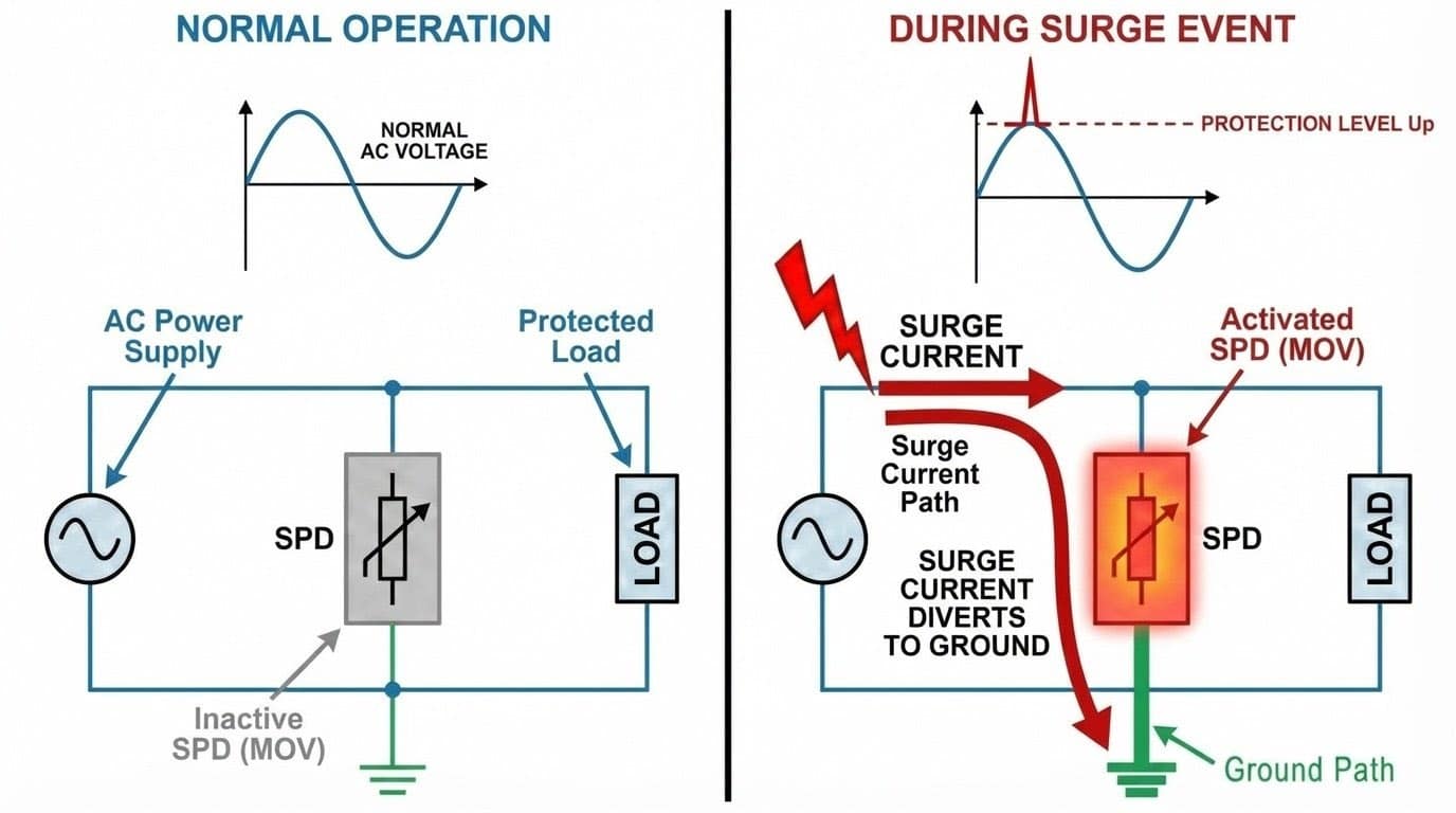
Key characteristics:
- Activates within microseconds when voltage exceeds a safe threshold
- Clamps voltage to a protection level (Up) typically between 1.0 and 2.5 kV
- Diverts surge current to ground while keeping the circuit operational
- Does not interrupt power like a circuit breaker — purely voltage limiting
1.1 Surge Protective Device vs. Other Protection Devices
| Device | Primary function | Protects against |
|---|---|---|
| Surge Protective Device (SPD) | Limits transient overvoltages in LV systems (<1 kV) | Lightning surges, switching transients |
| Circuit Breaker / Fuse | Interrupts overcurrent faults | Short circuits, overloads |
| Lightning Arrester (Air Termination) | Intercepts direct lightning strikes | Structural damage from direct strikes |
| Surge Arrester | MV/HV surge protection (>1 kV) | High-voltage transients in MV/HV systems |
"Lightning Arrester" refers to air termination rods that intercept direct strikes. "Surge Arrester" in IEC standards refers specifically to medium and high-voltage protection devices. For low-voltage applications (<1 kV), the correct term is Surge Protective Device (SPD).
For a full explanation of the differences, read our lightning arrester vs surge arrester comparison guide.
2. Why Low-Voltage Power Systems Need Surge Protection
Unprotected low-voltage systems face equipment losses of $5,000–$50,000 per surge event — costs that far exceed the 0.5–2% of installation value required for comprehensive SPD protection. Modern industrial equipment — VFDs (Variable Frequency Drives), inverters, PLCs (Programmable Logic Controllers), solar inverters — is highly vulnerable to transient overvoltages. A 3 kV surge from a nearby lightning strike can destroy components rated for 2.5 kV impulse withstand.
2.1 Four Common Surge Sources
1. Lightning-induced surges
- Indirect strikes within 1 km induce 6–10 kV spikes in power lines
- Direct strikes to overhead lines inject partial lightning current (10–200 kA)
2. Switching transients
- Motors, capacitor banks, and welding equipment generate 1–3 kV spikes at startup and shutdown
- Cumulative damage shortens equipment life by 30–50% in high-switching facilities
3. Grid disturbances
- Utility faults, load shedding, and transformer energisation create propagating voltage spikes of 2–5 kV
4. Equipment sensitivity
- VFDs: IGBT modules fail at 3–4 kV (replacement cost $5,000–$20,000)
- PLCs: memory corruption, I/O card damage, communication failures
- Solar inverters: DC-side surges destroy input stages ($10,000–$50,000+)
3. What Determines SPD Reliability Beyond the Datasheet
Two manufacturing factors — MOV vertical integration and 100% routine testing — determine whether an SPD delivers its rated protection consistently across every unit and every batch.
3.1 Vertical Integration — MOV Quality
The core component of any SPD is the Metal Oxide Varistor (MOV). Most brands outsource their MOVs, which leads to inconsistent quality. A reliable manufacturer controls the full process — from MOV chip production to final assembly — ensuring that clamping voltage and energy handling are precise and consistent across every batch.
3.2 100% Routine Testing vs. Batch Sampling
IEC standards set minimum testing requirements, but production consistency varies significantly between manufacturers.
- Standard practice: Many budget manufacturers test 1 in 50 units (batch sampling).
- Premium practice: 100% routine testing — every unit verified for V1mA (varistor voltage) and leakage current before leaving the factory.
For a broader look at how to evaluate SPD suppliers on these criteria, see our guide on choosing an SPD manufacturer in China.
4. How IEC 61643-11 Classifies and Tests Surge Protective Devices
IEC 61643-11 classifies surge protective devices into three types by installation location and lightning current withstand capacity, and mandates specific test waveforms that cannot be substituted between types. IEC 61643-11 is the global benchmark for low-voltage AC SPDs, defining classification, performance requirements, and test methods. It was updated in 2025 with enhanced testing protocols, stricter voltage tolerance requirements, and mandatory remote monitoring for large SPDs.

4.1 Classification: Type 1, 2, and 3
IEC 61643-11 classifies surge protective devices by installation location and lightning current withstand capacity:
- Type 1 (Class I): Main incoming protection — withstands direct and nearby lightning strikes
- Type 2 (Class II): Distribution board protection — handles induced surges and switching transients
- Type 3 (Class III): Point-of-use protection for sensitive equipment
4.2 Test Waveforms Explained
| Test waveform | Used for | Energy level | What it simulates |
|---|---|---|---|
| 10/350 µs | Type 1 | Very high | Direct lightning strike |
| 8/20 µs | Type 2, Type 3 | Medium | Induced surges, switching transients |
| 1.2/50 µs | Type 2, Type 3 | Voltage only | Open-circuit voltage spike |
| 10/350 µs + 8/20 µs | Type 1+2 (2025) | Very high (combined) | Direct strike immediately followed by residual surge — back-to-back test |
2025 update: The new combined back-to-back test (10/350 µs immediately followed by 8/20 µs, no cooling period) better simulates real lightning events. Type 1+2 SPDs must pass 15 complete cycles to meet the new standard. Look for "sequential combined test" in the certificate.
Type 1 surge protective devices are bulkier and more expensive because the 10/350 µs waveform delivers significantly more energy than 8/20 µs — longer duration means more joules transferred. This is why Type 1 is mandatory at the service entrance where direct lightning effects can occur.

4.3 IEC 61643-11 Certification Requirements
| Region / application | Requirement | Standard |
|---|---|---|
| European Union | Mandatory (CE marking) | EN 61643-11 |
| North America | Insurance requirement | UL 1449 |
| Solar PV systems | Mandatory (most countries) | IEC 61643-11 + IEC 61643-31 |
| Critical infrastructure | Strongly recommended | IEC 61643-11 |
How to verify genuine IEC 61643-11 certification
- Request the full test report PDF from an accredited laboratory (IEC 17025)
- Check the product label for certification marks (CE, UL, TÜV)
- Verify the certificate number with the issuing body
- "Compliant with" does not mean "Certified to" — confirm the difference
5. Main Types of Surge Protective Devices
Selection strategy: Most industrial facilities need Type 1+2 at the service entrance plus Type 2 at all sub-boards. Add Type 3 only for highly sensitive electronic equipment more than 15 m from the nearest Type 2.

5.1 Type 1 SPD — Service Entrance Protection
Primary function: Intercept high-energy surges from external sources (lightning, utility faults) before they enter the facility.
When required:
- Building has an external lightning protection system (LPS)
- High lightning exposure (tropical regions, hilltop locations)
- Overhead power line service entrance
- Critical infrastructure
Typical ratings:
- Iimp: 25 kA, 50 kA (10/350 µs per pole)
- Uc: 275 V (L-N) or 440 V (L-L) for 230/400 V TN-S systems
Type 1 SPDs are characterised by Iimp (10/350 µs impulse current), not In. The In parameter applies to Type 2 SPDs only.
Keep ground leads ≤0.5 m and straight. Long leads negate protection effectiveness through inductance.
For a detailed comparison, see our complete SPD type comparison guide and Type 1 product range.
5.2 Type 2 SPD — Distribution Board Protection
Primary function: Industrial workhorse — handles residual transients after Type 1, plus all internal switching surges.
When needed:
- Every sub-distribution board in industrial and commercial facilities
- Service entrance if no external LPS and medium lightning risk
- All panels with sensitive loads (VFDs, PLCs, inverters)
Typical ratings:
- In: 10 kA, 20 kA (8/20 µs) — 10 kA minimum for industrial
- Imax: 40–100 kA
- Uc: 275 V (TN-S), 320 V (TT systems)
View the TrilPeak Type 2 range and learn about circuit breaker and SPD coordination per IEC 61643-12.
5.3 Type 3 SPD — Point-of-Use Protection
Primary function: Final protection layer for extremely sensitive equipment when distance from the nearest Type 2 exceeds 10–15 metres.
When to use (optional for most facilities):
- Distance between Type 2 and equipment exceeds 15 m
- Extremely sensitive equipment: medical imaging, lab instrumentation, precision automation
- Equipment manufacturer warranty requires three-stage protection
Typical ratings:
- In: 5 kA (lowest energy capacity)
- Up: 0.8–1.5 kV
- Formats: plug-in modules, DIN rail mounted units
View Type 3 products and the complete Type 1 vs 2 vs 3 comparison.
5.4 Type 1+2 Combined Surge Protective Devices
Best of both worlds: A single device tested for both 10/350 µs (Iimp) and 8/20 µs (In) waveforms.
Typical ratings:
- Iimp: 7 kA, 12.5 kA, 15 kA, 25 kA (10/350 µs)
- In: 15–20 kA (8/20 µs)
Advantages over separate Type 1 + Type 2:
- Single device replaces two — simplifies installation
- Eliminates the 10 m coordination distance requirement
- Space-saving in compact panels
- Often more cost-effective
Check that the datasheet shows both Iimp AND In ratings with IEC 61643-11 certification. Some manufacturers incorrectly label Type 2 devices as "Type 1+2."
6. Key Parameters When Selecting a Surge Protective Device
Selection priority: Get Uc and In right first — these determine whether the SPD will work in your system. Then optimise Imax, Iimp, and Up.
6.1 Uc — Maximum Continuous Operating Voltage
If Uc is too low, the SPD fails prematurely or conducts incorrectly. If too high, the protection level Up increases, reducing effectiveness.
| System grounding | Nominal voltage | Min Uc (L-N) | Min Uc (L-L) | 2025 update |
|---|---|---|---|---|
| TN-S / TN-C-S | 230/400 V | 275 V | 440 V | Unchanged |
| TT system | 230/400 V | 345 V (use 350 V or 385 V rated SPD) | 550 V | Increased from 320 V |
| IT system | 400 V | N/A (no phase-to-ground) | 440–480 V | Unchanged |
| TN-S / TN-C-S | 277/480 V (North America) | 320 V | 550 V | Unchanged |
Retrofit alert: existing TT systems with 320 V SPDs installed before 2025 are grandfathered but should be upgraded during the next maintenance cycle. All new installations from 2026 onward require 350 V+ rated SPDs for TT systems.
Selection formulas (IEC 61643-11:2025):
- TN systems: Uc ≥ 1.15 × U0
- TT systems: Uc ≥ 1.5 × U0 (increased from 1.45 in the 2025 edition)
- IT systems: Uc ≥ 1.73 × U0
For a complete engineering guide to Up, Uc, In, Imax, and response time, see our SPD key parameters guide.
6.2 In — Nominal Discharge Current
Peak current (8/20 µs) the device can discharge 15 times per IEC protocol without failure.
| Risk level | Recommended In | Applications |
|---|---|---|
| High (frequent storms, exposed locations, critical equipment) | 15–20 kA | Telecom towers, exposed industrial plants |
| Medium (suburban/industrial areas) | 10–15 kA | Most commercial and industrial buildings |
| Low (dense urban, underground service) | 5–10 kA | City centres, underground-fed buildings |
6.3 Imax and Iimp — Maximum Surge Capacity
Imax is the peak 8/20 µs current the device survives in a single extreme event. Typically Imax = 2–5 × In. For industrial sites: Imax ≥ 60 kA (Type 2), ≥ 100 kA (Type 1+2).
Iimp (Type 1 only) is the peak 10/350 µs current defining capability against direct lightning effects.
| Application | Recommended Iimp |
|---|---|
| Standard building with external LPS | 25 kA per IEC 62305 |
| High-exposure facility (towers, tall structures) | 50 kA |
| Utility-scale solar/wind, extensive overhead cables | 50–100 kA |
No Iimp rating on the datasheet means Type 2 only — unsuitable as a service entrance device.
6.4 Up — Voltage Protection Level
Up is the residual let-through voltage that reaches equipment during a surge. Lower Up means better protection. Up must be lower than the equipment's impulse withstand voltage.
| Equipment category | Typical withstand | Recommended Up |
|---|---|---|
| Cat II (PLCs, VFDs, electronics) | 2.5 kV | Up ≤ 2.0 kV |
| Cat III (distribution switchgear) | 4.0 kV | Up ≤ 3.0 kV |
6.5 Short-Circuit Withstand and Backup Protection
When an SPD fails short-circuit after a severe surge, the resulting fault current can be catastrophic without backup protection. IEC 61643-11 Clause 8.3.2.3 mandates external overcurrent protection rated per the SPD datasheet.
Mandatory backup protection:
- Fuse: typically 63–125 A gG-type for Type 2 SPDs
- MCB: check the SPD datasheet for compatible ratings (C32–C63)
- Position backup protection upstream and as close as possible to the SPD
Real incident: SPD installed on 80 kA busbar without a fuse. Lightning caused busbar vaporisation, panel fire, $45,000 damage, and three days of downtime. Always install backup protection.
Explore our surge backup protector (SCB) range specifically designed for SPD coordination.
6.6 Grounding Conductor Size Requirements per IEC 61643-11
Grounding conductor size is the most frequently searched IEC 61643-11 compliance topic — and the most commonly violated. Engineers frequently use standard 2.5 mm² PE wire instead of the IEC-specified size, which increases impedance and reduces protection effectiveness significantly.
| SPD type | Min. copper conductor | Max. length | Application |
|---|---|---|---|
| Type 1 | 16 mm² | 0.5 m | Service entrance |
| Type 2 | 10 mm² | 0.5 m | Distribution board |
| Type 3 | 4 mm² | 1.0 m | Point-of-use |
Do not use standard 2.5 mm² building PE wire as the SPD grounding conductor. Insufficient cross-section increases impedance and significantly reduces surge protection effectiveness.
In IEC 61643-11 context, "earthing conductor" and "grounding conductor" are synonymous. "Earthing" is the preferred term in European, British, Australian, and Indian standards; "grounding" is more common in North American practice. The technical requirements above apply identically regardless of terminology.
6.7 Remote Status Indication (2025 New Requirement)
Large SPDs must now include remote monitoring capability to track protection status without physical inspection.
When required:
- SPDs with In > 20 kA
- SPDs with backup fuse > 63 A
- Recommended for all Type 1 and Type 1+2 at the service entrance
How it works: Dry contact output — closes when SPD is healthy, opens when failed. Connects to alarm lamp, PLC, or building management system.
7. Where to Install Surge Protective Devices in an LV Distribution System
Effective surge protection requires a coordinated, multi-stage system: Type 1+2 at the service entrance, Type 2 at every sub-distribution board, and optionally Type 3 at point-of-use — a single device at one location is never sufficient. Surges enter at multiple points, voltage can re-escalate in long cable runs, and different surge sources require different protection levels.
7.1 Three-Stage Protection
| Stage | SPD type | Location | Purpose |
|---|---|---|---|
| Stage 1 | Type 1 or Type 1+2 | Main distribution board (service entrance) | Intercept external surges — lightning, grid faults |
| Stage 2 | Type 2 | Sub-distribution boards throughout the facility | Handle residual transients and internal switching surges |
| Stage 3 | Type 3 | Point-of-use (≤5 m from equipment) | Final protection for highly sensitive devices |
7.2 Installation Best Practices
1. Lead length — keep it short and straight
Target: ≤0.5 m total lead length from SPD to busbar and to ground.
- At surge frequencies (~1 MHz), even 1 m of wire has ~1 µH inductance
- Voltage drop across a 2 m lead during a 20 kA surge = 2+ kV — more than the SPD's Up
- Long leads completely negate protection capability
Do not coil leads for aesthetics. Straight and short beats neat and long.

2. Grounding connection
- Connect directly to main grounding busbar
- Conductor size: ≥16 mm² Cu (Type 1), 10 mm² (Type 2)
- TN-S: connect to PE bar
- TT: low-impedance path to installation earth electrode (≤10 Ω)
- Each SPD needs its own dedicated ground path — do not daisy-chain
3. Coordination distance between stages
Minimum requirement: 10 m cable between Type 1 and Type 2.
If distance < 10 m: install a decoupling inductor (10–20 µH) between stages, or use a Type 1+2 combined device (which has no coordination distance requirement).
4. Backup protection
- Rate per SPD manufacturer datasheet — never exceed the specified rating
- Position upstream and close to the SPD
- High Isc sites (>50 kA): consider dedicated external overcurrent protection
5. Visual accessibility for maintenance
- Status indicators (green/red windows) must be visible without disassembling the panel
- Connect remote monitoring contacts to BMS (Building Management System)/SCADA for automatic alerts
7.3 Example: SPD Layout in a Manufacturing Facility
Facility: Metal fabrication plant, 400 V TN-S system, 1600 kVA transformer (Isc = 35 kA at MDB)
| Location | SPD type | Key specifications | Backup protection |
|---|---|---|---|
| Main Distribution Board | Type 1+2 | Iimp = 25 kA, In = 20 kA, Uc = 440 V, Up = 1.5 kV | 125 A gG fuse |
| Production Floor Sub-Panel | Type 2 | In = 20 kA, Imax = 80 kA, Uc = 440 V, Up = 1.5 kV | 80 A gG fuse |
| Control Room Sub-Panel | Type 2 | In = 10 kA, Imax = 60 kA, Uc = 440 V, Up = 1.2 kV | 63 A gG fuse |
| Critical PLC Rack | Type 3 | In = 5 kA, Up = 1.2 kV | Internal to rack |
After implementing this scheme, the facility eliminated 3–4 annual VFD and PLC failures ($15,000 each), achieving an 18-month zero-failure record during a high storm activity period.
8. Common Mistakes in Industrial and PV SPD Applications
40–50% of SPD installations contain at least one critical error that significantly reduces or completely eliminates surge protection — the most common being wrong Uc selection, lead lengths over 0.5 m, and missing backup protection. From auditing hundreds of industrial installations, these recurring mistakes cause the majority of field failures.
8.1 Mistake 1: Ignoring System Grounding Type
Error: 3-pole SPD in TT system (missing N-PE protection), or Uc = 275 V in a TT system (which requires 320 V minimum).
Solution: TN-S → 3+1 pole, Uc = 275 V. TT → 4-pole with N-PE protection, Uc = 320 V minimum.
8.2 Mistake 2: Wrong Uc Selection
Error: Using Uc = 385 V for both TN-S (needs 275 V) and TT (needs 320 V). Higher Uc means higher Up, which means worse protection.
8.3 Mistake 3: No Backup Protection
Real incident: Solar PV plant, SPD on 80 kA busbar without a fuse. Lightning caused busbar vaporisation, panel fire, $45,000 damage, three days of downtime.
8.4 Mistake 4: Long or Coiled Connection Leads
Physics: Lead inductance ~1 µH per metre. During a 20 kA surge: V = L × di/dt = 1 µH × (20 kA / 1 µs) = 2 kV added voltage — defeats the SPD's Up rating entirely.
Solution: Mount SPD adjacent to busbars, ≤0.5 m total lead length, straight routing (no coils).
8.5 Mistake 5: Poor Coordination Between SPD Stages
Error: Type 1 and Type 2 only 3 m apart. The faster Type 2 activates first and overloads.
Solution: ≥10 m cable between stages. If <10 m, install a 10–20 µH decoupling inductor.

8.6 Mistake 6: Missing DC SPDs in PV Systems
Risk: DC string surges destroy PV fuses, optimisers, and inverter DC inputs.
Solution: DC side — Type 2 SPD per IEC 61643-31, Uc ≥ 1.2 × Voc, In ≥ 20 kA. AC side — Type 2 at inverter output plus Type 1 at grid connection. See our solar surge protection guide.
8.7 Mistake 7: Set-and-Forget Mentality
Hidden danger: SPDs degrade internally (varistor cracks) but indicators remain green — equipment is unprotected.
Inspection schedule:
- Quarterly: visual check of indicators and damage — 2–5 min per panel
- Annually: connection tightness, corrosion, remote contact test — 10–15 min per panel
- After storms: immediate inspection following nearby lightning
- 5–10 years: replace even if indicators show OK
9. 2026 Trends in Surge Protection for LV Power Systems
9.1 Smart SPDs with IoT Connectivity
Real-time monitoring of voltage, current, temperature, and surge event counting. Predictive alerts warn before complete failure. Cloud dashboards provide multi-site SPD status visibility and integration with BMS and SCADA systems.
9.2 Hybrid SPD Technologies
Combining gas discharge tubes (GDT), metal oxide varistors (MOV), and TVS diodes in a single device delivers lower Up (1.0–1.2 kV vs 1.5–2.0 kV traditional), longer service life, lower leakage current, and 30–40% smaller form factor.
9.3 IEC 61643-11:2025 — Enhanced Standards
Refined test methods, stricter safety requirements (thermal runaway prevention, flammability testing), enhanced coordination guidelines, and mandatory remote monitoring for large SPDs. When specifying SPDs, verify compliance with the 2025 edition — some products still reference the 2011 edition.
9.4 Surge Protection for Energy Storage Systems (ESS)
Battery energy storage at 800–1500 V DC with bidirectional power flow requires DC SPDs rated for battery voltage (1000 VDC or 1500 VDC), Type 1+2 for outdoor ESS containers, and coordinated AC and DC side protection.
9.5 EV Charging Infrastructure Protection
Type 1+2 at the main distribution board. Type 2 at each charging pedestal (In ≥ 20 kA, Imax ≥ 80 kA). IP54 minimum enclosures (IP65 for outdoor). Signal line SPDs for CAN bus and Ethernet communication interfaces.
9.6 Sustainability and Circular Economy
Modular replaceable cartridges, recyclable aluminium housings, halogen-free polymers, and EPD (Environmental Product Declaration) documentation. Modular designs extend service life to 10+ years and reduce waste from whole-unit replacement.
10. SPD Selection Checklist for LV Power Systems
10.1 Step 1: Identify System Characteristics
- ☐ System voltage and frequency documented (e.g. 400 V, 50 Hz)
- ☐ Grounding system type confirmed (TN-S, TN-C-S, TT, IT)
- ☐ Prospective short-circuit current calculated at each SPD location (Isc in kA)
- ☐ Single-line diagram available showing all distribution boards
10.2 Step 2: Assess Surge and Lightning Risk
- High risk: Type 1+2 at main board + Type 2 at ALL sub-boards (exposed location, overhead lines, external LPS, frequent storms, critical equipment)
- Medium risk: Type 2 at main board + Type 2 at sub-boards (suburban/industrial, underground service, moderate storm activity)
- Low risk: Type 2 at main board minimum (dense urban, underground service, rare storms)
10.3 Step 3: Select SPD Types and Ratings
- ☐ Type 1 or Type 1+2 at service entrance (if high risk or external LPS present)
- ☐ Type 2 at each major distribution board
- ☐ Type 3 for sensitive equipment within 5 m (if highly sensitive loads)
- ☐ Type 1+2 verified with both Iimp AND In ratings
10.4 Step 4: Verify Key Parameters
- ☐ Uc matches system voltage and grounding type (TN-S 230/400 V: 275 V L-N; TT 230/400 V: 320 V L-N)
- ☐ In adequate for lightning risk (high: 15–20 kA; medium: 10–15 kA; low: 5–10 kA)
- ☐ Imax sufficient (Type 2 minimum: 40 kA; recommended: 60–80 kA)
- ☐ Up lower than equipment impulse withstand (Cat II: ≤2.0 kV; Cat III: ≤3.0 kV)
10.5 Step 5: Plan Installation Details
- ☐ Backup protection specified per SPD datasheet
- ☐ Connection lead length ≤0.5 m confirmed in installation drawings
- ☐ Coordination distance ≥10 m between SPD stages (or decoupling choke specified)
- ☐ Grounding conductor size per IEC 61643-11 (≥16 mm² for Type 1, ≥10 mm² for Type 2)
- ☐ Remote monitoring contacts specified (if BMS/SCADA integration required)
10.6 Step 6: Plan Maintenance and Replacement
- ☐ Quarterly visual inspection scheduled
- ☐ Annual detailed inspection including connection torque check
- ☐ Post-storm inspection procedure documented
- ☐ 5–10 year SPD replacement plan in asset management system
Learn to identify when your SPD needs replacement in our surge protector end-of-life guide.
11. Frequently Asked Questions
11.1 What Is New in IEC 61643-11:2025?
The 2025 edition (released June 2025) introduces three main changes. First, TT systems now require a minimum 345 V SPD rating (use 350 V or 385 V rated devices) — increased from 320 V, based on updated temporary overvoltage analysis. Second, Type 1+2 combined devices must now pass back-to-back testing: 10/350 µs pulse immediately followed by 8/20 µs pulse with no cooling period, 15 complete cycles. Third, remote monitoring is now mandatory for SPDs with In > 20 kA or backup fuse > 63 A.
Timeline: Both 2024 and 2025 editions are accepted through 2027. From 2028 onwards, only 2025-compliant SPDs apply to new projects.
11.2 What Is the Difference Between Type 1 and Type 2 Surge Protective Devices?
Type 1 is tested with the 10/350 µs waveform (high energy, simulates partial lightning current) and rated by Iimp — typically 12.5 kA, 25 kA, or 50 kA. It is installed at the service entrance to intercept external surges. Type 2 is tested with the 8/20 µs waveform (medium energy, simulates induced surges) and rated by In — typically 10 kA or 20 kA. It is installed at sub-distribution boards throughout the facility. A Type 2 with Imax = 100 kA (8/20 µs) will still fail against a 10 kA surge at 10/350 µs because of the 10× energy difference. You cannot substitute Type 2 for Type 1 at the service entrance.
11.3 My SPD Indicator Light Turned Red — What Does It Mean?
Red indicator means the SPD has failed and is no longer providing protection. Replace within 24 hours — your equipment is currently unprotected. Green means operational; red means replace immediately. Common causes: thermal disconnector activation from MOV degradation, surge overload exceeding Imax, normal wear-out after 5–15 years, or wrong Uc causing premature conduction. If multiple SPDs failed simultaneously, inspect all connected equipment for surge damage.
11.4 What Is the Difference Between Type 1 and Type 1+2 Combined SPDs?
Type 1 is tested for 10/350 µs only and must be paired with a separate Type 2 downstream with a 10 m minimum coordination distance. Type 1+2 combined is a single device tested for both waveforms, replacing both devices in one unit with no coordination distance requirement. Type 1+2 is recommended for new installations and compact panels. Use separate Type 1 only when very high Iimp is required (50–100 kA) or in legacy retrofits.
11.5 Should I Use a Fuse or MCB for SPD Backup Protection?
Both are acceptable per IEC 61643-11. gG fuses (63–125 A) offer the fastest clearing time, highest breaking capacity (100–200 kA), and lowest cost — preferred for industrial and high Isc sites. MCBs (C32–C63) are resettable but slower and have lower breaking capacity (6–25 kA) — suitable for commercial buildings and where accessibility is a priority. Always check the SPD datasheet for the maximum compatible backup protection rating.
11.6 Why Is 10 Metres Coordination Distance Required Between Type 1 and Type 2?
Cable inductance between SPD stages creates impedance that prevents Type 2 from conducting prematurely during Type 1 operation. At 10 m (~10 µH), the voltage drop during a fast surge is sufficient to allow Type 1 to discharge first. If Type 2 conducts simultaneously with Type 1, it shares surge current, degrades faster, and fails prematurely. If physical distance is less than 10 m, install a 10–20 µH decoupling inductor between stages, or use a Type 1+2 combined device.
11.7 How Often Should I Replace Surge Protective Devices?
Replace immediately when the indicator turns red. For preventive replacement: every 10 years for critical facilities (hospitals, data centres, production lines), 12–15 years for standard industrial and commercial, 8–10 years in high lightning exposure areas. Always replace after severe surge events even if the indicator shows green — cumulative stress may have reduced remaining capacity below a detectable threshold.
11.8 Can I Use the Same SPD for TN-S and TT Systems?
No. TT systems require higher Uc because during ground faults, the voltage between line and PE can rise to approximately 1.45× nominal voltage before the RCD trips. TN-S: Uc = 275 V (L-N), 440 V (L-L). TT: Uc = 320 V (L-N), 550 V (L-L). Installing a 275 V SPD in a TT system L-PE position causes the SPD to conduct during every ground fault, triggering premature thermal disconnector activation.
11.9 Do I Need Separate SPDs for Solar PV DC and AC Sides?
Yes. AC and DC systems require independent, separate SPD protection. An AC SPD provides zero protection for DC circuits. Install Type 2 DC SPDs per IEC 61643-31 (Uc ≥ 1.2 × Voc,max, In ≥ 20 kA) at the PV array combiner box and inverter DC input. Install Type 2 AC SPDs at the inverter output and Type 1+2 or Type 2 at the grid connection point. See our solar surge protection guide for the full architecture.
11.10 Can I Install an SPD with an RCD?
Yes, with precautions. The preferred configuration is SPD upstream of the RCD to avoid nuisance tripping. If downstream installation is required: select an SPD with leakage current <0.5 mA per phase, use a Type A or Type B RCD (not Type AC) for better surge immunity, and consider an S-type (time-delayed) RCD with 40–80 ms delay. Calculate total leakage — SPD plus connected equipment — to confirm it stays below 50% of the RCD rating.
11.11 Is IEC 61643-11 the Same as UL 1449?
No. IEC 61643-11 is the international standard (Europe, Asia, Africa, South America) and classifies devices as Type 1, 2, and 3, using 10/350 µs for Type 1 and 8/20 µs for Type 2/3 test waveforms. UL 1449 is the North American standard with different test methods using a combination wave (1.2/50–8/20 µs). Most reputable SPD manufacturers certify products to both standards for global projects.
11.12 What Is the Correct Grounding Conductor Size for Type 1 SPD per IEC 61643-11?
Minimum 16 mm² copper conductor, maximum connection length 0.5 m. Type 2 requires minimum 10 mm², Type 3 requires minimum 4 mm² with maximum 1.0 m length. Do not use standard 2.5 mm² building PE wire — insufficient cross-section increases impedance and significantly reduces surge protection effectiveness.
12. IEC 61643-11 Standard Overview
12.1 Standard History and Evolution
- IEC 61643-1 (1992): Original standard for low-voltage SPDs
- IEC 61643-11 (2011): Restructured edition with enhanced test requirements
- IEC 61643-11:2025: Latest edition — updated TT voltage requirements, Type 1+2 combined testing, mandatory remote monitoring
12.2 IEC 61643 Series Structure
| Standard | Scope | Application |
|---|---|---|
| IEC 61643-11 | AC power systems (low-voltage) | Buildings, industrial, commercial |
| IEC 61643-12 | Selection and application guide | System design and coordination |
| IEC 61643-31 | Solar photovoltaic systems | DC side of PV arrays |
12.3 Relationship with Other Standards
- EN 61643-11: European harmonised version (identical technical content)
- UL 1449: North American standard (different test methods and classification)
- IEC 62305: Lightning protection standard (specifies where SPDs should be installed)
- IEC 60364: Low-voltage electrical installations (references IEC 61643-11 for SPD requirements)
13. How TrilPeak Can Help
TrilPeak manufactures IEC 61643-11 certified surge protective devices with in-house MOV production and 100% routine testing — the two factors that determine real-world SPD reliability. Our product range covers low-voltage power distribution, renewable energy, and critical infrastructure. Vertically integrated manufacturing — including in-house MOV chip production — and 100% routine testing ensure consistent performance across every unit.
13.1 AC Power Surge Protection
- Type 1 SPDs: Iimp = 50 kA, modular design for field replacement
- Type 2 SPDs: In = 10 kA and 20 kA, Up ≤ 2.0 kV, available with remote monitoring dry contacts or Modbus
- Type 3 SPDs: In = 5 kA, Up ≤ 1.5 kV
- Type 1+2 combined: Iimp = 7–25 kA, single device eliminates coordination distance
View the complete AC range: TrilPeak AC Surge Protectors, including single-phase and three-phase models.
13.2 DC and Solar PV Surge Protection
- DC SPDs for solar PV: IEC 61643-31 certified, 600–1500 VDC, In = 20 kA
13.3 Communication and Data Line Protection
- Network and data line SPDs: Ethernet (PoE/PoE+), RS-485, Modbus RTU, 4–20 mA, coaxial
TrilPeak manufactures IEC 61643-11 certified surge protective devices with in-house MOV production and 100% routine testing — the two factors that determine real-world SPD reliability. Our product range covers low-voltage power distribution, renewable energy, and critical infrastructure. Vertically integrated manufacturing — including in-house MOV chip production — and 100% routine testing ensure consistent performance across every unit. For panel-level and factory installations specifically, see our industrial surge protector selection guide for the three-question type selection method.
14. Conclusion
Surge protection is not optional — it is a 0.5–2% investment that protects equipment worth 50–500× more. The difference between protected and unprotected systems comes down to four factors: correct SPD selection, proper installation, quality manufacturing, and regular maintenance. The cost of comprehensive SPD protection — 0.5–2% of total electrical installation value — is minimal compared to potential equipment damage, production downtime, and safety incidents from a single unprotected surge event.
Four things that determine whether your surge protection works:
- Selection: Match Uc to system grounding type. Specify adequate In and Iimp for your lightning exposure level. Verify Up is below equipment withstand voltage.
- Installation: Short leads (≤0.5 m), correct coordination distance (≥10 m between stages), and manufacturer-specified backup protection are non-negotiable.
- Quality: Look for manufacturers with 100% routine testing, in-house MOV production, and accredited third-party certification.
- Maintenance: Quarterly visual inspections, spare parts inventory, and smart SPDs with remote monitoring for critical and unmanned sites.
Related Resources & Standards
Looking for IEC 61643-11 Certified Surge Protective Devices?
TrilPeak supplies Type 1, Type 2, Type 3, and DC SPDs for industrial, solar PV, and critical infrastructure applications. CE certified · IEC 61643-11 · engineering reply within 24h.