
What Is a Solar Power Plant? Types, Components & Surge Protection Requirements
Quick Answer
A solar power plant is an electrical generation facility that converts sunlight into grid-compatible AC electricity using PV panels, inverters, transformers, and associated protection equipment. Three types exist by scale: utility-scale (≥1 MW), commercial & industrial (C&I, 100 kW–1 MW), and rooftop/distributed (≤100 kW).
Every solar power plant requires surge protection at two points: DC side — between the PV array and inverter input (IEC 61643-31, Type 2 DC SPD); AC side — at the inverter AC output and grid connection point (IEC 61643-11, Type 1+2 or Type 2 AC SPD). Lightning is the primary external threat; inverter MPPT switching is the primary internal threat.
For EPC contractors and solar project developers, understanding what a solar power plant consists of is inseparable from understanding what can destroy it. Each major component presents a distinct surge exposure profile — and specifying the wrong protection, or omitting it entirely, is one of the leading causes of inverter and equipment failure in the field. This guide covers solar power plant types, all key components, and the IEC-standard surge protection requirements for each.
1. What Is a Solar Power Plant?
A solar power plant is an energy generation facility that converts solar radiation into electrical energy at scale. Unlike a residential rooftop system, a solar power plant is designed for continuous grid-connected operation, with monitoring, protection, and control systems appropriate for a commercial or industrial electrical installation.
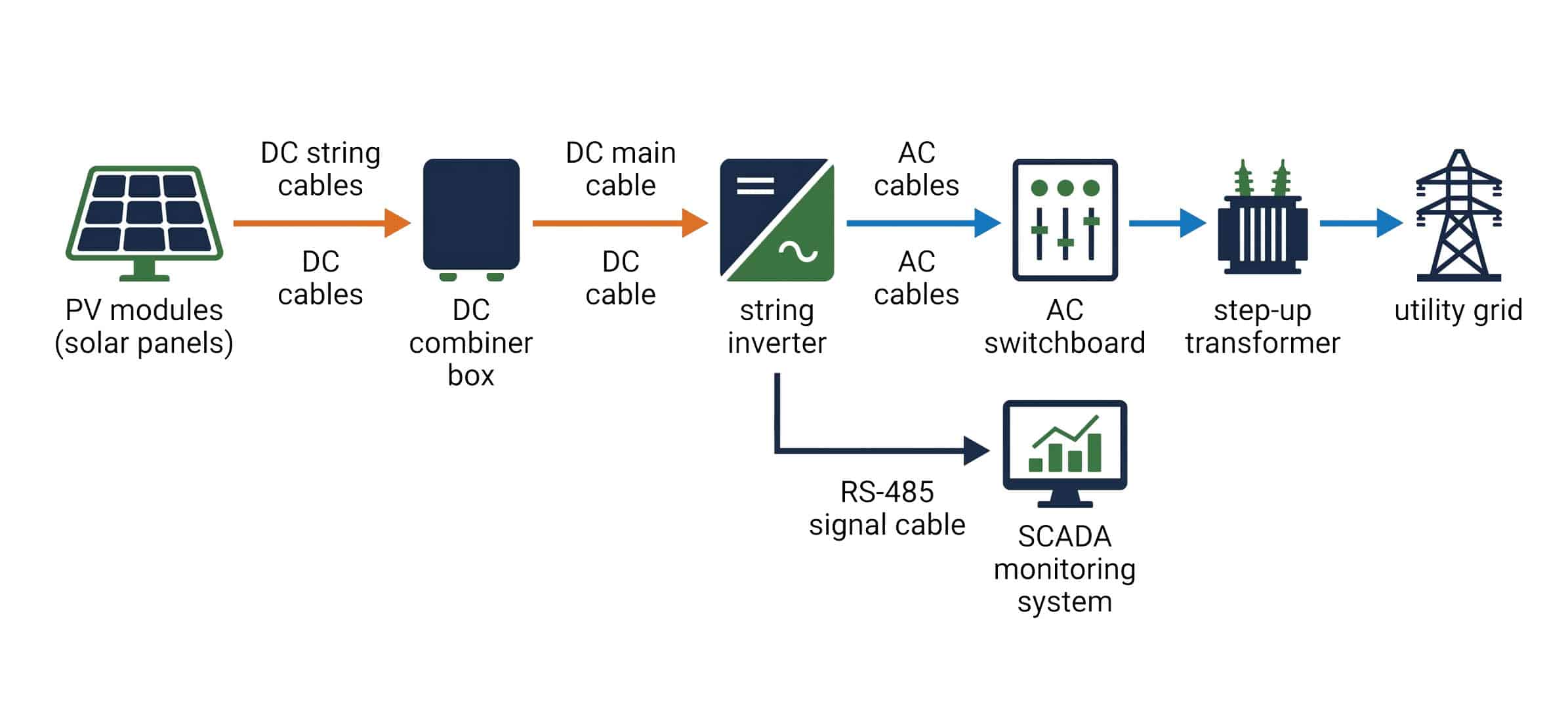
The fundamental conversion process is the same regardless of scale: photovoltaic cells in the solar panels absorb photons and release electrons, generating direct current (DC) electricity. This DC power is collected, combined, and fed into inverters that convert it to alternating current (AC) at grid-compatible voltage and frequency. The AC output is then stepped up by transformers for transmission and injected into the utility grid or consumed on-site.
What distinguishes a solar power plant from a simple rooftop installation is the engineering complexity at scale: string and array design, DC combiner boxes, central or string inverters, medium-voltage transformers, SCADA monitoring, grid protection relays, and — critically — a coordinated surge protection system covering both the DC and AC sides of the installation.
2. Types of Solar Power Plant
Solar power plants are classified by scale, application, and whether they feed into the utility grid or serve on-site loads directly.
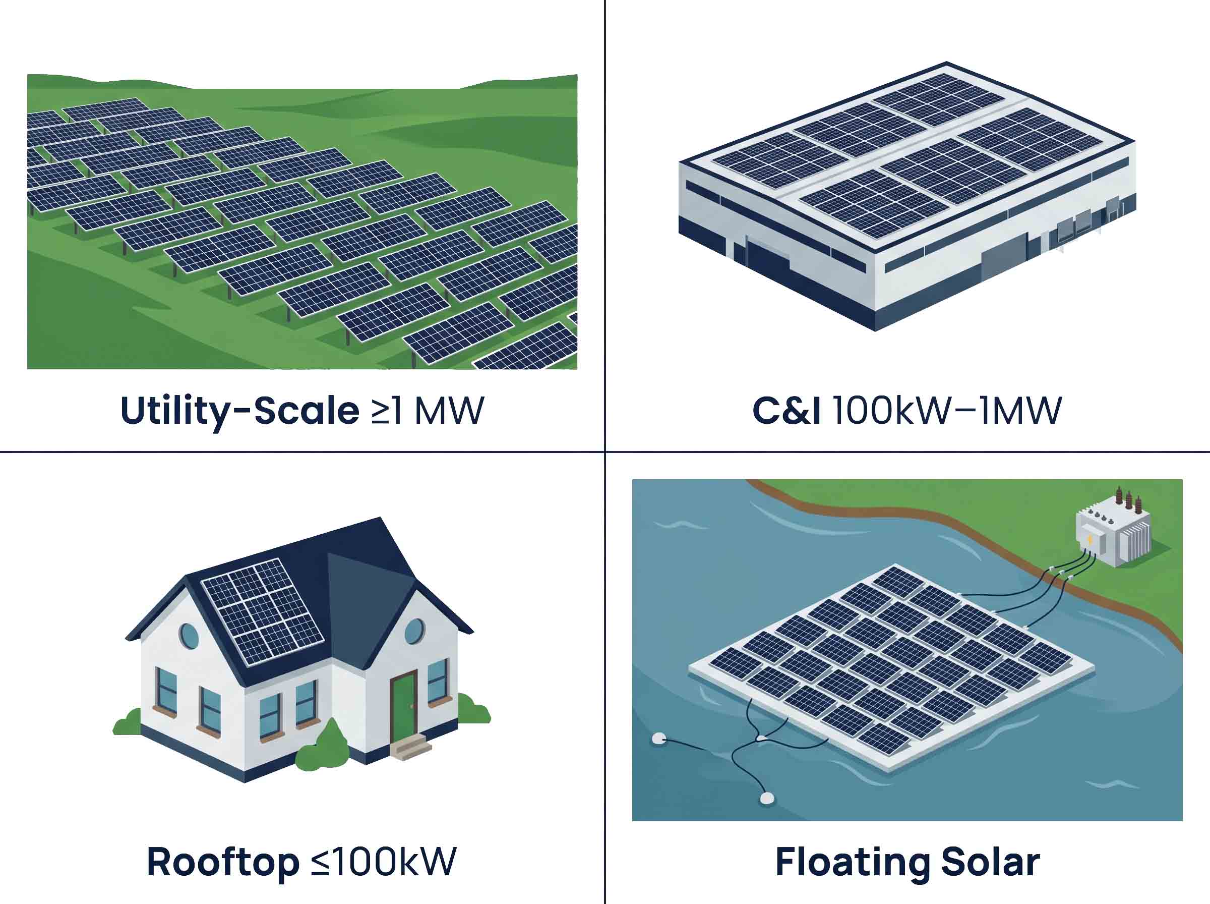
2.1 Utility-Scale Solar (≥1 MW)
Utility-scale solar farms typically range from 1 MW to several hundred MW and connect directly to the transmission or sub-transmission grid via medium-voltage or high-voltage transformers and substations. They use central inverters (500 kW–5 MW per unit) or large string inverters arranged in inverter stations, and occupy 20–25 hectares per 10 MW of installed capacity.
From a surge protection perspective, utility-scale plants face the highest lightning exposure due to open terrain, large cable runs, and extensive DC wiring networks. IEC 62305-2 risk assessment is mandatory at this scale, and the results almost universally require an external lightning protection system (LPS) plus coordinated SPDs across the entire electrical installation.
2.2 Commercial & Industrial (C&I) Solar (100 kW–1 MW)
C&I installations are mounted on industrial rooftops, carparks, and open ground adjacent to commercial facilities. They typically serve the facility's own load, with excess power exported to the grid. String inverters (15–100 kW) or multi-string inverters dominate this segment.
C&I installations present a mixed surge threat: external lightning exposure from rooftop or open-ground mounting, and internal switching surges from industrial loads sharing the same distribution system. Both DC-side and AC-side SPDs are required.
2.3 Rooftop / Distributed Solar (≤100 kW)
Small commercial and residential systems use single-phase or three-phase string inverters feeding either the building's distribution system or the low-voltage grid. While the individual scale is smaller, surge damage to inverters in this segment is the most common single cause of warranty claims and field failures across the solar industry.
2.4 Floating Solar (Floatovoltaic)
Floating solar on reservoirs, irrigation ponds, and water treatment facilities is a fast-growing segment. Open water increases lightning exposure, high humidity accelerates SPD degradation, and remote locations complicate replacement. Higher IP-rated SPDs (IP65 minimum) and remote monitoring contacts are strongly recommended for all floating installations.
| Type | Scale | Inverter Type | Grid Connection | Primary SPD Concern |
|---|---|---|---|---|
| Utility-scale | ≥1 MW | Central / large string | MV/HV grid | High lightning exposure, long DC cable runs |
| C&I | 100 kW–1 MW | Multi-string / string | LV/MV grid | Lightning + industrial switching surges |
| Rooftop/distributed | ≤100 kW | String / micro | LV grid | Inverter switching, grid disturbances |
| Floating | Any | String / central | LV/MV grid | High lightning exposure, humidity, remote access |
3. Solar Power Plant Components
A complete solar power plant consists of seven major component groups. Understanding the electrical function of each is essential for specifying correct surge protection at every point in the system.
3.1 PV Modules (Solar Panels)
PV modules are the primary energy conversion element. Silicon photovoltaic cells are wired in series within each module to produce a nominal DC voltage — typically 30–50 V per module at standard test conditions. Modules are then connected in strings of 8–25 units to reach the inverter's MPPT input voltage range: up to 1,000 V DC for residential and C&I systems, and up to 1,500 V DC for utility-scale installations.
PV modules themselves are vulnerable to surge damage via the DC wiring that connects them. Lightning striking within 1–2 km of the array induces transient overvoltages on the DC strings through electromagnetic coupling. These transients travel along the string wiring toward the inverter's DC input — the most expensive single component in the system. Without DC-side SPDs, the inverter absorbs this energy directly.
3.2 Mounting Structures
Ground-mount structures (fixed-tilt or single-axis trackers) and rooftop racking systems provide mechanical support for PV modules. Mounting structures must be electrically bonded to the PV array frame and connected to the site's equipotential bonding and earthing system. Inadequate bonding between the mounting structure and earth is one of the most common installation deficiencies that undermines SPD performance — an SPD can only discharge surge current if it has a low-impedance path to earth.
3.3 DC Combiner Boxes
DC combiner boxes collect the DC output from multiple PV strings onto a common busbar, combining them into a single DC feed to the inverter. A typical combiner box handles 4–16 strings and contains string fuses or DC circuit breakers, a DC disconnect switch, and — in a correctly designed system — a Type 2 DC SPD per IEC 61643-31.
The DC combiner box is the optimal location for the first stage of DC surge protection: it is electrically close to the string outputs, provides a convenient mounting point, and already contains the fusing needed for SPD backup protection. An SPD installed here protects the entire downstream system — cabling, disconnects, and inverter — from string-level surge events.

Note: TrilPeak's PV combiner box includes an integrated Type 2 DC SPD (IEC 61643-31, Imax 40 kA) as standard, eliminating the need for a separate SPD installation at this point.
3.4 DC Cabling
DC cabling connects PV strings to combiner boxes, combiner boxes to inverters, and — in utility-scale systems — inverters to DC collection busbars. DC cable runs in large installations can extend hundreds of metres, significantly increasing the inductive loop area that couples to external lightning electromagnetic fields. The longer the DC cable run, the higher the induced surge voltage reaching the inverter.
For DC cable runs exceeding 10 metres between the array and inverter, or where the cable route is exposed to direct lightning, IEC 61643-31 and IEC 62305-4 both support installing additional DC SPDs at the inverter's DC input terminals as a second protection stage.
3.5 Solar Inverters
The inverter is the central electrical component of any PV system — and the most expensive single item to replace. It converts DC power from the PV array into grid-synchronized AC power via high-frequency IGBT switching. Modern string inverters contain MPPT circuits that continuously adjust the DC operating point; a DC-AC conversion stage switching at 10–20 kHz; grid monitoring and protection (anti-islanding, frequency/voltage monitoring); and communications interfaces — RS-485, Ethernet, or Wi-Fi for SCADA integration.
The inverter is simultaneously a victim of surges (sensitive electronics destroyed by transients from array or grid) and a source of surges (MPPT switching and output switching generate transients propagating to both DC array and AC distribution). This dual role means protection is required on both sides. For more on how MOV-based SPDs clamp these transients, see our MOV surge protector guide.
3.6 AC Collection and Distribution
On the AC side, inverter outputs are combined via AC collection cables and AC switchboards before connection to the step-up transformer. In C&I systems, the inverter AC output typically connects directly to the facility's main distribution board or a dedicated solar AC panel.
AC-side surge events originate from grid switching operations, utility grid faults, lightning on the MV network propagating through the transformer, and the inverter's own AC switching. A Type 1+2 AC SPD at the grid connection point — or a Type 2 AC SPD at each inverter's AC output — provides the necessary clamping.
3.7 Transformers and Grid Connection
Utility-scale and larger C&I plants use step-up transformers to raise inverter AC output voltage (typically 270–800 V AC) to medium voltage (10–35 kV) for grid connection. The transformer attenuates some surge energy between LV and MV sides but also provides a coupling path for MV-side surges to enter the LV system. At the grid connection point, a high-voltage surge arrester (IEC 60099-4) on the MV terminals protects against direct lightning on the MV network.
4. Why Solar Power Plants Are Especially Vulnerable to Surges
Solar power plants face a more severe surge environment than most commercial buildings for four structural reasons.
Open terrain and elevated exposure. Ground-mount solar farms are typically located in flat, open land with no surrounding structures to provide shielding. The arrays themselves are often the tallest objects in the landscape for hundreds of metres. Lightning ground flash density in such environments is higher, and there is no shielding from adjacent buildings.
Extensive DC wiring networks. A 1 MW solar plant may contain 5–10 km of DC string cable. This cable network forms large inductive loops that efficiently couple to the electromagnetic field of a nearby lightning strike. The induced surge voltage is proportional to the loop area and the rate of change of the lightning current — both of which are large in open-field utility installations.
Sensitive power electronics at the termination point. Every surge that travels along the DC wiring terminates at the inverter's DC input stage — a densely integrated power electronics assembly with semiconductor devices rated for operating conditions, not lightning-energy transients. Without SPDs, a single nearby lightning strike routinely exceeds the inverter's maximum input surge rating.
Continuous unattended operation. Solar plants operate continuously with minimal on-site staffing. An SPD that reaches end-of-life may remain in place for months before a maintenance visit identifies it. Remote monitoring contacts on SPDs — alerting the SCADA system when an SPD needs replacement — are not optional for any professionally managed solar installation. See our guide on when to replace a surge protector for inspection intervals.
5. Surge Protection Requirements for Solar Power Plants
Surge protection for a solar power plant must cover three distinct points in the system. Each requires a different SPD type, rated to a different standard.
5.1 DC Side — PV Array to Inverter Input (IEC 61643-31)
The DC side of a PV system operates at high voltage (up to 1,500 V DC) with continuous current flow. SPDs for the DC side must be specifically rated for DC applications — standard AC SPDs are not suitable, as DC arcing behaviour during a fault condition is fundamentally different from AC and requires different SPD internal construction and thermal protection.
The governing standard is IEC 61643-31. Key parameters to specify:
- Ucpv (maximum continuous DC operating voltage): Must be ≥ 1.2 × Voc of the PV string under worst-case temperature conditions. For a 1,000 V system: Ucpv ≥ 1,000 V. For a 1,500 V system: Ucpv ≥ 1,500 V.
- In (nominal discharge current, 8/20 µs): Minimum 20 kA for most installations; 40 kA recommended for high-lightning-risk zones or long cable runs.
- Up (voltage protection level): Must be below the inverter's maximum input surge rating, typically Up ≤ 2.5 kV for 1,000 V systems.
TrilPeak's DC SPD range for solar PV: TPK-7 PV (Type 1+2, Iimp 7 kA, for installations with external LPS) and TPK-40 PV (Type 2, In 40 kA, standard DC protection). Both are IEC 61643-31 certified and rated for 1,000 V DC systems.
5.2 AC Side — Inverter Output to Grid (IEC 61643-11)
The AC side connects to the utility grid and is exposed to all the surge events that affect any grid-connected installation: lightning on the MV network, grid switching operations, and power factor correction capacitor switching. The AC-side SPD must be rated per IEC 61643-11.
- With external LPS: Type 1+2 AC SPD at the main AC connection point — mandatory per IEC 62305-4
- Without external LPS, moderate lightning risk: Type 2 AC SPD (In ≥ 20 kA) at inverter AC output or main AC switchboard
- Without external LPS, high lightning risk: Type 1+2 AC SPD recommended at main connection, Type 2 at each inverter AC output
5.3 Signal and Communications Lines
Modern solar plants use RS-485 or Ethernet for inverter monitoring, SCADA communication, and weather station data. These signal cables run across the plant site alongside DC string cables and are equally susceptible to lightning-induced transients. Signal line SPDs per IEC 61643-21 should be installed at every communications cable entry point to the inverter, combiner box, or monitoring enclosure.
TrilPeak's RS-485 signal SPD and Ethernet SPD series are rated to IEC 61643-21 and designed for DIN-rail installation inside inverter and monitoring enclosures.
| Protection Point | Standard | SPD Type | Key Parameters | TrilPeak Series |
|---|---|---|---|---|
| DC combiner box output | IEC 61643-31 | Type 2 DC | Ucpv ≥ 1,000/1,500 V; In ≥ 20 kA | TPK-40 PV |
| DC input (with external LPS) | IEC 61643-31 | Type 1+2 DC | Iimp ≥ 7 kA; Ucpv ≥ 1,000 V | TPK-7 PV |
| Inverter AC output / main AC board | IEC 61643-11 | Type 2 AC | In ≥ 20 kA; Uc ≥ 275 V | TPK-20 / TPK-40 |
| AC main (with external LPS) | IEC 61643-11 | Type 1+2 AC | Iimp ≥ 7 kA; Uc ≥ 275 V | TPK-7 / TPK-12.5 |
| RS-485 / Modbus lines | IEC 61643-21 | Signal SPD | Rated for RS-485 signal levels | TPKXJ series |
| Ethernet monitoring lines | IEC 61643-21 | Signal SPD | Cat5e/Cat6 rated | TPKX RJ45 series |
6. SPD Selection Guide for Solar EPC Contractors
6.1 Step 1 — Determine Lightning Risk Level
- Obtain the ground flash density (GFD) for the project site (flashes/km²/year) from national meteorological data
- GFD < 2: Moderate risk — Type 2 DC and AC SPDs are the minimum requirement
- GFD 2–5: Elevated risk — Type 1+2 DC SPD at combiner box; Type 1+2 AC SPD at main connection
- GFD > 5: High risk — full IEC 62305-2 risk assessment required; external LPS plus Type 1+2 SPDs throughout
6.2 Step 2 — Check System Voltage
- 1,000 V DC system: specify DC SPDs with Ucpv ≥ 1,000 V
- 1,500 V DC system: specify DC SPDs with Ucpv ≥ 1,500 V — confirm the specific model is rated for 1,500 V DC
- AC side (standard IEC market 230/400 V): Uc ≥ 275 V
6.3 Step 3 — Confirm External LPS Status
- External LPS installed → Type 1+2 mandatory on both DC and AC sides per IEC 62305-4
- No external LPS → Type 2 minimum; Type 1+2 recommended for GFD > 2
6.4 Step 4 — Specify Remote Monitoring
For any professionally managed solar installation, specify SPDs with remote signalling contacts (NO/NC dry contact output). Wire the SPD status contacts into the plant SCADA system so that SPD end-of-life generates an alert. An SPD past end-of-life provides no protection — remote monitoring is the only reliable way to detect this in an unattended installation. Use our SPD Selector Tool to identify the correct series for your project parameters.
7. Frequently Asked Questions
7.1 Do solar panels need surge protection?
Yes — protection is required on the wiring connected to the panels, not on the panels themselves. Lightning striking within 1–2 km of a PV array induces transient overvoltages of several kilovolts on the DC string cables. These transients travel toward the inverter and destroy its input electronics if no DC SPD is installed. The inverter, combiner box electronics, and monitoring systems are the components at risk.
7.2 Where should surge protectors be installed in a solar system?
Two locations are mandatory. First, inside the DC combiner box or at the inverter DC input — a Type 2 DC SPD per IEC 61643-31, rated for the system's maximum DC voltage (1,000 V or 1,500 V). Second, at the inverter AC output or main AC switchboard — a Type 2 AC SPD per IEC 61643-11. If the installation has an external lightning protection system, Type 1+2 devices replace Type 2 at both locations.
7.3 What is the difference between AC and DC surge protectors for solar?
DC SPDs must handle continuous DC bias voltage without degrading, and their thermal protection must safely interrupt DC arc current — which does not self-extinguish at zero-crossing as AC does. Using an AC SPD on a DC circuit is a safety hazard and a standards violation. Always use IEC 61643-31 certified DC SPDs on the PV array side and IEC 61643-11 certified AC SPDs on the inverter output side.
7.4 How often do solar SPDs need to be replaced?
MOV-based SPDs degrade with each surge event. In high-lightning regions, DC SPDs in a utility-scale plant may need replacement every 2–5 years depending on lightning activity. All TrilPeak SPDs include a visual status indicator (green = functional, red = replace) and optional remote signalling contacts for SCADA integration. Replace any SPD showing a fault indicator immediately.
7.5 Is surge protection required by IEC standards for solar PV?
Yes. IEC 62305-4 requires surge protective measures for electrical systems within structures whenever an external lightning protection system is installed. Additionally, many inverter manufacturers specify minimum SPD requirements in their installation manuals; failure to install the specified SPDs may void the inverter warranty. IEC 61643-31 is the product standard for DC PV SPDs and defines the test and performance requirements they must meet.
7.6 What is the difference between a 1,000 V and 1,500 V solar system for SPD selection?
1,500 V DC systems have become standard in utility-scale installations because they reduce DC cable losses and allow longer string lengths. However, SPDs specified for 1,000 V DC systems are not suitable for 1,500 V applications — the Ucpv rating must match or exceed the system voltage. Using a 1,000 V-rated SPD on a 1,500 V system will cause the SPD to conduct continuously, overheat, and fail. Always verify the Ucpv rating on the SPD datasheet before specifying for a 1,500 V system.
8. Conclusion
A solar power plant is more than an array of panels — it is a complete electrical system in which every component from PV string to utility grid connection presents a defined surge exposure point. The inverter is the highest-value and most vulnerable element in that chain, and it sits at the intersection of two independent surge threats: induced lightning transients traveling inward from the DC array, and grid-side switching surges traveling inward from the AC network.
Correct surge protection requires addressing both sides independently, with SPDs rated to the appropriate standard — IEC 61643-31 for the DC side, IEC 61643-11 for the AC side — and sized to the system voltage, lightning risk level, and whether an external LPS is present. Signal and communications lines carry the same lightning risk as power cables and require their own protection stage.
For EPC contractors and project developers, specifying surge protection at the design stage is the lowest-cost, highest-reliability decision in the project. Replacing a failed inverter in a commissioned solar plant — including downtime, logistics, and labour — costs far more than a complete SPD specification across the entire installation.
Related Resources & Standards
Need IEC 61643-31 certified DC SPDs for your solar project?
TrilPeak supplies Type 2 and Type 1+2 DC SPDs for 1,000 V and 1,500 V PV systems, plus AC SPDs and signal line protection — all IEC certified, DIN-rail mounted, with optional remote monitoring contacts. CE certified · IEC 61643-31 · engineering reply within 24h.