Lightning Strike Counter: What It Is, How It Works & Why Your LPS Needs One (2026)

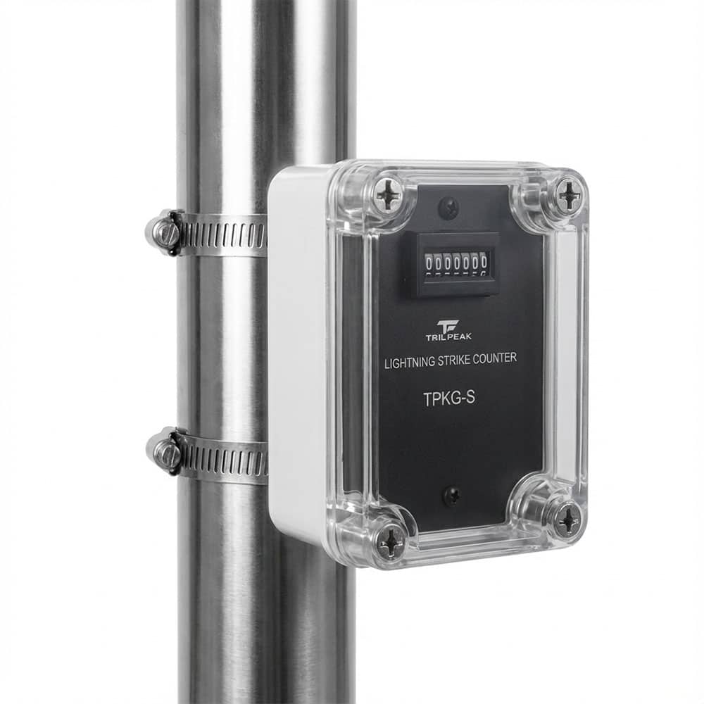
Quick Answer: What Is a Lightning Strike Counter?
A lightning strike counter is a passive device installed on an LPS down-conductor — the cable that connects a lightning rod to the grounding system — that counts every time a lightning current flows through it. It requires no power supply and uses the electromagnetic energy of the lightning impulse itself to advance the mechanical counter. Each count represents a confirmed lightning event at that structure. Counter readings are used to trigger the extraordinary LPS inspections required by IEC 62305-3 Clause 7 after any known strike, and to assess cumulative stress on down-conductor joints, connections, and earth electrodes.
Jump to: How it works · Where to install · IEC 62305-3 & maintenance · How to read the data · TrilPeak TPKG series · FAQ
An LPS — air terminals, down-conductors, earth electrodes — is designed to intercept lightning and safely conduct the current to ground. But once installed, how do you know it has actually been hit? How do you know the down-conductor joints and earth electrodes have been stressed? How do you decide when an extraordinary inspection is needed?
Without a lightning strike counter, the answer is: you don't. A lightning event can occur at night, during a storm when no one is present, or at a remote structure where visual inspection is impractical. The counter solves this problem with a single, robust, maintenance-free device that creates a permanent, tamper-evident record of every confirmed lightning event at the structure.
What Is a Lightning Strike Counter?
A lightning strike counter (LSC) is defined by IEC 62561-6 as a device "intended to count the number of lightning strikes based on current flowing in a conductor." It is classified as a Lightning Protection System Component (LPSC) and is covered by the IEC 62561 series, which governs all LPS hardware from air terminals and down-conductors to clamps, bonding conductors, and earth electrodes.
The lightning strike counter is installed on the LPS down-conductor — the conductor that physically connects the air terminal (lightning rod or ESE terminal) to the earth-termination system. Every time lightning strikes the air terminal, current flows down this conductor to ground. The counter detects this current event and increments its display by one.
Lightning Strike Counter vs Surge Counter — an Important Distinction
These are two fundamentally different devices serving different purposes, and they must not be confused:
| Device | Installed On | What It Counts | Purpose |
|---|---|---|---|
| Lightning Strike Counter (e.g. TPKG-3M, TPKG-S) |
LPS down-conductor (lightning rod → earth) | Direct lightning strikes to the LPS air terminal | LPS maintenance monitoring — trigger inspections of down-conductors, joints, earth electrodes |
| Surge Counter (e.g. TPKJ-E) |
SPD earthing wire / DIN rail in distribution panel | Surge events handled by the SPD (induced surges, switching transients, indirect strikes) | SPD maintenance monitoring — assess SPD degradation and schedule replacement |
A lightning strike counter on an LPS down-conductor counts direct lightning events at the structure. A surge counter on an SPD earth conductor counts surge events at the electrical installation, which include induced surges from nearby strikes and switching transients — not just direct hits. The two devices answer completely different maintenance questions and are not interchangeable.
How a Lightning Strike Counter Works
The operating principle of a mechanical lightning strike counter is entirely passive — it requires no battery, no power supply, and no external wiring beyond its mounting on the down-conductor.
Detection Principle: Magnetic Field Induction
When lightning current flows through the down-conductor, it generates an intense, rapidly changing magnetic field around the conductor. The lightning strike counter's sensing element — an inductive pickup or current loop — is positioned around the down-conductor and detects this magnetic field. The induced electromagnetic pulse drives a mechanical stepping mechanism that advances the counter display by exactly one digit.
This is the same physical principle as a current transformer: no direct electrical contact with the conductor is needed. The counter body clamps around or over the down-conductor without breaking the conductor or inserting any component into the current path. The lightning current continues to flow to earth unimpeded, and the counter records the event.
Trigger Threshold
The counter does not respond to every small electrical event — it has a defined minimum trigger current below which it does not count. For lightning strike counters installed on LPS down-conductors per IEC 62561-6, the typical minimum counting current is 3 kA (8/20 µs waveform). The maximum withstand current is 100 kA (10/350 µs waveform) — well above the peak currents defined for any Lightning Protection Level in IEC 62305-1.
This threshold ensures the counter responds to genuine lightning events while ignoring the small induced currents that flow in down-conductors during nearby strikes or switching transients on the power network.
No Power Supply Required
The mechanical lightning strike counter extracts all the energy it needs to advance the counter from the electromagnetic field of the lightning event itself. There are no batteries to replace, no power cables to connect, and no possibility of a missed count due to a power failure. The counter operates equally in the middle of a thunderstorm as in full sun — at any temperature, in any weather condition, for the lifetime of the LPS.
IEC 62561-6 classification: Lightning strike counters are classified by type of current counted — Type I LSC counts impulse discharge currents (10/350 µs, representing direct lightning current) and Type II LSC counts nominal discharge currents (8/20 µs, representing surge currents). The TPKG series counters installed on LPS down-conductors are Type I/II capable, with the mechanical detection responding to the steep current front of both waveforms above the 3 kA threshold.
Where to Install a Lightning Strike Counter
Installation position on the down-conductor is important for both correct counting and practical accessibility during inspections.
Position on the Down-Conductor
The counter must be installed on a straight, vertical section of the down-conductor, positioned so that all lightning current from the air terminal flows through it. The standard installation point is just above the test clamp (disconnection link) near ground level — typically at a height of 0.3–1.5 m above ground, depending on accessibility requirements and local practice.
This position has two advantages: it is downstream of all down-conductor joints and the air terminal connection, meaning all current from a strike passes through it; and it is at a height that allows easy visual reading of the counter display during routine LPS inspections without requiring ladders or elevated access.
Installation rule: Keep the counter at least 25 cm away from any sharp bends, test clamps, or disconnection links. Proximity to these features can distort the local magnetic field and affect counting accuracy. Install on a straight run of conductor only.
One Counter per Down-Conductor
In an LPS with multiple down-conductors (as required for larger structures by IEC 62305-3 Table 4), a counter should ideally be installed on each down-conductor. A single counter on one down-conductor only records events where significant current took that specific path — in a multi-conductor system, lightning current splits between all parallel paths, so a counter on only one conductor may undercount total events at the structure. Multiple counters also reveal uneven current distribution, which can indicate poor bonding, a defective earth electrode, or a preferred strike point.
Outdoor IP Requirements
IEC 62561-6 requires that lightning strike counters installed outdoors have a minimum enclosure protection of IP43. In practice, counters are exposed to the full range of outdoor conditions — rain, dust, UV, temperature extremes, coastal salt spray, and industrial pollution — and IP65 or higher is strongly recommended for most installations. The TPKG-S achieves IP67, making it suitable for even the most exposed outdoor installations including coastal structures, industrial facilities, and tropical climates.
IEC 62305-3 & LPS Maintenance
IEC 62305-3 Clause 7 establishes the framework for LPS inspection and maintenance. Understanding how a lightning strike counter fits into this framework is the key to getting value from the device.
Routine Inspection Intervals
IEC 62305-3 Clause 7 requires periodic inspections of the complete LPS at intervals that depend on the LPS class and the environment. National implementations of the standard (BS EN 62305-3, NF EN 62305-3, and others) typically define intervals of 1 year for LPS Class I and II, and 2 years for Class III and IV in normal environments. Harsher environments — coastal, industrial, high-lightning-density areas — may require shorter intervals.
During a routine inspection, the counter reading is recorded and compared against the previous inspection reading. Any increase confirms that one or more lightning events occurred at the structure since the last inspection.
Extraordinary Inspection After a Known Strike
This is the most important function of the lightning strike counter. IEC 62305-3 Clause 7 requires an extraordinary inspection after any known lightning strike to the structure — not just at the next scheduled interval. Without a counter, "known strike" typically means the building owner noticed damage or witnesses observed a strike. With a counter, any increase in the reading is conclusive evidence of a lightning event, regardless of whether it was observed.
The extraordinary inspection triggered by a counter reading increase covers the complete LPS: all air terminal connections, down-conductor sections and joints, test clamps, bonding connections, and earth electrodes. These elements experience intense electromagnetic forces and thermal stress during a lightning event — particularly at the peak currents associated with LPL I/II structures (up to 200 kA). Even if no visible damage is present, connections can loosen and earth electrode contacts can degrade.
The risk of not having a counter: A lightning strike occurs at night during a storm. No one observes it. The down-conductor joint has loosened under the electromagnetic force of the 100+ kA current. The next storm arrives three months later. The joint fails under the second event, the down-conductor arc-discharges to a nearby metal installation, and a fire starts. A counter reading at the first event would have triggered the inspection that found the loose joint. This is exactly the scenario IEC 62305-3 Clause 7 extraordinary inspections are designed to prevent.
Counter Data and the Maintenance Decision
The counter reading does not tell the engineer how severe the lightning event was — only that a current above the trigger threshold (3 kA) flowed through the down-conductor. A single count could represent a modest 10 kA event or a maximum 200 kA direct strike. For this reason, any increase in the counter reading, however small, should trigger at least a targeted visual inspection of the down-conductor and its connections.
Multiple counts in a short period — or a high cumulative count on a structure in a high-lightning-density area — should trigger a full inspection including earth resistance measurement and continuity testing of all bonding conductors.
How to Read and Use the Counter Data
Reading the Counter
The mechanical lightning strike counter displays a cumulative count that increments by one for each qualifying lightning event. The TPKG-3M displays up to 99,999 events (5 digits); the TPKG-S displays up to 9,999,999 events (7 digits). During each LPS inspection, the technician reads and records the current count. The difference between the current and previous reading gives the number of lightning events since the last inspection.
The TPKG-3M is resettable — the count can be reset to zero after each inspection if required by the maintenance protocol. The TPKG-S maintains a cumulative non-resettable record as standard, providing a permanent lifetime history of lightning activity at the structure.
What a Count Increase Means in Practice
Any increase from the previous reading means at least one lightning current event above 3 kA occurred on that down-conductor since the last inspection. The appropriate response depends on the magnitude of the increase and the LPS class:
| Counter Reading Change | Recommended Action |
|---|---|
| +1 since last inspection | Visual inspection of all down-conductor sections, joints, test clamps, and bonding connections. Check air terminal condition. Record findings. |
| +2 or more since last inspection | Full extraordinary inspection per IEC 62305-3 Clause 7: visual inspection + earth resistance measurement + continuity testing of all bonds + mechanical check of all clamps and connections. |
| High cumulative count (structure in high-Ng area) | Consider shortening routine inspection interval. Review earth electrode condition — repeated high-current events accelerate corrosion at the electrode interface. |
| Counter on one down-conductor shows counts; others show zero | Investigate current distribution — check for unequal earth electrode resistance or a preferred strike point. Consider adding or relocating air terminals. |
Single Counter vs Multiple Counters
In a structure with multiple down-conductors, a single counter on one conductor gives a lower-bound count of lightning events — some events may have distributed most current to other conductors and not triggered the single counter. Multiple counters on all down-conductors give a more complete picture: the counter with the highest reading on a given conductor indicates that path carries the most current, which may reflect the proximity of the nearest air terminal or an imbalance in the earth-termination system.
TrilPeak TPKG Series: Lightning Strike Counters for LPS Down-Conductors
TrilPeak's TPKG series provides mechanical lightning strike counters designed for installation on the down-conductors of any IEC 62305-compliant LPS — lightning rods, ESE terminals, Faraday cage systems. Both models require no power supply, operate passively from the electromagnetic energy of the lightning event, and are built for permanent outdoor installation.
| Specification | TPKG-3M | TPKG-S |
|---|---|---|
| Type | Mechanical lightning strike counter | Mechanical lightning strike counter |
| Min. current recorded | 3 kA (8/20 µs) | 3 kA (8/20 µs) |
| Max. current withstand | 100 kA (10/350 µs) | 100 kA (10/350 µs) |
| Register capacity | 0 – 99,999 (5 digits) | 0 – 9,999,999 (7 digits) |
| Resettable | Yes | Cumulative (non-resettable) |
| IP rating | — | IP67 |
| Temperature range | −20°C to 65°C | −20°C to 65°C |
| External material | Stainless steel 304 | ABS |
| Installation | Stainless steel hoop on down-conductor | Stainless steel hoop — Type A or Type B |
| Power supply | None required | None required |
| Dimensions (mm) | 150 × 70 × 40 | 110 × 80 × 70 |
| Best for | Standard installations where reset after inspection is preferred | Harsh outdoor environments, coastal/industrial, permanent lifetime record required |
Which Model to Choose
The TPKG-3M is the standard choice for most LPS installations. Its stainless steel 304 construction handles outdoor conditions well, and the resettable counter makes it straightforward to track events per inspection period — reset at each inspection, and the next reading directly shows events since the last visit.
The TPKG-S is the choice for demanding environments: coastal structures exposed to salt spray, industrial facilities with chemical atmospheres, tropical climates with high humidity and UV exposure. Its IP67 rating means it can be submerged in water up to 1 metre without ingress — far exceeding what any outdoor LPS installation will experience. The 7-digit display and cumulative non-resettable design provide a permanent lifetime record of all lightning activity at the structure, which is valuable for insurance documentation and long-term maintenance planning.
Note on surge counting: If you also need to monitor the number of surge events handled by your SPDs — to assess SPD degradation and plan replacement — TrilPeak's TPKJ-E Surge Counter is the dedicated device for that purpose. It installs on a DIN rail in the distribution panel and counts surge events on the SPD earthing conductors, which is a completely separate monitoring function from the LPS down-conductor strike counting described in this article.
Ready to add lightning strike monitoring to your LPS installation? TrilPeak's TPKG series counters install in minutes on any IEC 62305-compliant down-conductor — no wiring, no power supply, no maintenance.
TPKG-3M — View Product TPKG-S IP67 — View ProductFAQ: Lightning Strike Counters
IEC 62305-3 does not mandate lightning strike counters as a required component of every LPS. They are classified under IEC 62561-6 as optional monitoring accessories. However, IEC 62305-3 Clause 7 does require extraordinary inspections after any known lightning strike to the structure — and without a counter, the only way to know whether the LPS has been struck is direct observation or visible damage. In practice, a counter is the most reliable and cost-effective way to comply with the extraordinary inspection requirement, particularly for unattended structures, remote sites, or buildings in high-lightning-density areas. Many national LPS standards and insurance requirements effectively make counters the expected standard of care.
The counter should be read at every scheduled LPS inspection — at minimum annually for LPS Class I/II, or every two years for Class III/IV per IEC 62305-3 Clause 7. If the building is in a high-lightning-density area (high Ng), or if a severe thunderstorm is known to have passed over the structure, checking the counter sooner is good practice. Any increase in the reading since the last inspection should trigger at minimum a visual inspection of all down-conductor sections, joints, and bonding connections, as required by the extraordinary inspection provisions of IEC 62305-3.
A single lightning flash typically consists of multiple return strokes — the visible flickering of lightning is each individual stroke. Each return stroke that exceeds the counter's trigger threshold (3 kA) may cause the counter to increment. A single flash with three return strokes above threshold could therefore show as three counts. This is consistent with the definition in IEC 62561-6, which counts "impulses" rather than "flashes." In practice, for LPS maintenance purposes this distinction is not critical — any increase in the counter reading confirms that significant lightning current has flowed through the down-conductor and warrants an inspection.
Install the counter on a straight, vertical section of the down-conductor, just above the test clamp (disconnection link) near ground level — typically 0.3 to 1.5 m above ground. This position ensures all lightning current from the air terminal passes through the counter, places the display at a readable height for inspection without requiring elevated access, and keeps the counter away from the mechanical stress zone around the test clamp. Maintain at least 25 cm clearance from any bends, clamps, or disconnection links to avoid distortion of the magnetic field that drives the counter mechanism. IEC 62561-6 does not specify an exact height — follow the manufacturer's installation instructions for the specific model.
A lightning strike counter (such as the TrilPeak TPKG-3M or TPKG-S) is installed on the LPS down-conductor — the cable connecting a lightning rod to the earth-termination system. It counts direct lightning strikes to the LPS air terminal, with a trigger threshold of 3 kA. Its purpose is to support LPS maintenance by confirming when direct lightning events have occurred. A surge counter (such as the TrilPeak TPKJ-E) is installed on the SPD earthing conductor or DIN rail in the distribution panel. It counts surge events handled by the SPD, including induced surges from nearby strikes and switching transients, with a much lower trigger threshold (0.2 kA). Its purpose is to monitor SPD degradation and plan replacement. The two devices answer completely different questions and are used in different parts of the lightning protection system.
Conclusion
A lightning strike counter is one of the simplest, most cost-effective components in an IEC 62305 lightning protection system. It requires no power, no maintenance, and no commissioning — clamp it to the down-conductor and it works for the life of the LPS. What it provides in return is something no inspection schedule alone can deliver: a reliable, tamper-evident record of every confirmed lightning event at the structure.
For LPS engineers and facilities managers, the counter reading is the trigger for the most important maintenance action in IEC 62305-3: the extraordinary inspection after a known strike. Every joint, clamp, and bonding connection that experienced the electromagnetic forces of a lightning event should be verified before the next storm arrives. The counter makes this possible even when no one was present to observe the strike.
Related Resources
TrilPeak Lightning Strike Counter Products
- TPKG-3M Lightning Strike Counter — mechanical, stainless steel 304, resettable, for standard LPS down-conductor installations
- TPKG-S Lightning Strike Counter — mechanical, IP67, 7-digit cumulative display, for harsh outdoor environments
- TPKJ-E Surge Counter — electronic, DIN rail, RS485/Modbus, for monitoring SPD surge events in distribution panels
Technical Guides
- What Is a Lightning Protection System? — IEC 62305 overview: external LPS components, internal LPS, and SPD coordination
- TrilPeak LPS Product Range — air terminals, down-conductors, earth electrodes and LPS accessories
- Type 1 SPD Guide — the SPD installed at the LPS/LV installation interface, coordinated with external lightning protection
- Type 1 SPD: Carbon Spark Gap vs MOV — how Type 1 SPD technology handles 10/350 µs lightning current
- When to Replace a Surge Protector — using SPD status indicators and surge event data to time replacement
- IEC 61643-11 Explained — SPD classification, test waveforms, and Type 1/2/3 requirements
Standards Referenced
- International Electrotechnical Commission. (2010). IEC 62305-3:2010 — Protection against lightning — Part 3: Physical damage to structures and life hazard (2nd ed.). IEC. https://webstore.iec.ch/publication/6794
- International Electrotechnical Commission. (2023). IEC 62561-6:2023 — Lightning protection system components (LPSC) — Part 6: Requirements for lightning strike counters (LSCs). IEC. https://webstore.iec.ch/publication/67893
- International Electrotechnical Commission. (2017). IEC 60529:2013+AMD1:2016 — Degrees of protection provided by enclosures (IP Code). IEC. https://webstore.iec.ch/publication/61002
- International Electrotechnical Commission. (2005). IEC 62305-1:2010 — Protection against lightning — Part 1: General principles. IEC. https://webstore.iec.ch/publication/6791