Solar Combiner Box: Complete Guide to DC & PV Combiner Boxes for Solar Panels

Quick Answer: Solar Combiner Box
What it is: A solar combiner box (also called a PV combiner box or DC combiner box) is an electrical enclosure that collects DC output from multiple solar panel strings, combines them onto a common busbar, and routes the combined power to the inverter — while providing overcurrent protection, surge protection, and a safe disconnect point.
When you need one: When your PV system has 3 or more strings connected in parallel. For 1–2 strings, most modern inverters with built-in MPPT inputs are sufficient.
Key components inside: DC PV fuses (IEC 60269-6) or DC MCBs, Type 2 DC SPD (IEC 61643-31), DC busbar, DC isolator switch, PE ground bar — all inside a weatherproof enclosure.
DC vs AC: A DC combiner box handles raw PV power before the inverter (600–1500V DC). An AC combiner box aggregates AC outputs from multiple inverters. They are not interchangeable — DC arcs do not self-extinguish.
1. What Is a Solar Combiner Box? (PV Combiner Box Defined)
A solar combiner box is a weatherproof electrical enclosure installed between the solar PV array and the inverter that collects DC output from multiple strings, provides overcurrent and surge protection, and routes combined power to the inverter through a single safe disconnect point. Also called a PV combiner box, DC combiner box, or photovoltaic combiner box, it replaces the impractical alternative of running a separate pair of DC cables from every string directly to the inverter.
Without a combiner box, a large solar installation would require running a separate pair of DC cables from every string directly to the inverter. A 12-string commercial rooftop system would mean 24 individual DC cables — an installation nightmare and a significant source of wiring error and fault risk. The solar combiner box solves this by centralising all string connections into one organised, protected, and serviceable point.
Beyond simple cable consolidation, the modern PV combiner box is a complete protection hub: it houses the fuses that protect each string independently, the DC SPD that guards against lightning and surge damage, and the isolator switch that allows safe disconnection of the entire array for maintenance — all inside a single enclosure designed to withstand outdoor installation conditions for the life of the solar system.

1.1 Solar Combiner Box vs Junction Box: What's the Difference?
A solar junction box is the small sealed plastic box on the back of each individual solar panel — a panel-level component. A solar combiner box is a separate system-level enclosure that combines the outputs of multiple strings. These two terms are sometimes confused, but they refer to very different components. The junction box contains bypass diodes and MC4 connector leads and is integral to the panel itself. The combiner box is far larger, contains active protection devices (fuses, SPD, isolator switch), and is separately installed during system construction. When professionals in the solar industry refer to a combiner box, they always mean the string-level or array-level combiner — not the panel junction box.
2. What Does a Solar Combiner Box Do? 5 Key Functions
A solar combiner box performs five distinct functions — string current aggregation, overcurrent protection, transient overvoltage protection, safe isolation, and string monitoring — each critical to system safety, performance, and longevity. Understanding what a solar combiner box does in a PV system goes beyond "combining wires."
2.1 String Current Aggregation
Each solar string generates DC current at the string voltage (typically 200–1500V depending on system design). The combiner box collects the DC+ and DC− cables from every string and connects them in parallel on the positive and negative busbars inside the enclosure. The combined output current equals the sum of all string currents — for example, four strings each producing 10A deliver a combined 40A DC output to the inverter.
2.2 Overcurrent Protection Per String
Each string input passes through a dedicated DC PV fuse (or DC MCB in MCB-equipped models) before reaching the busbar. If one string develops a short circuit or reverse fault, its fuse interrupts only that string — leaving the remaining strings fully operational. Without per-string protection, a faulty string could draw reverse current from healthy strings, causing overheating, panel damage, and potential fire.
DC PV fuses in combiner boxes must be rated to IEC 60269-6, which specifically covers fuses for photovoltaic DC applications at 1000V or 1500V DC. Standard AC fuses are not suitable — they cannot reliably interrupt DC fault currents.
2.3 Transient Overvoltage Protection (DC SPD)
The DC Surge Protective Device (DC SPD) inside the solar combiner box is the primary defence against lightning-induced surges and switching transients on the PV array wiring. When a transient voltage spike occurs — from a lightning strike within 1–2 km of the array — the SPD clamps the voltage to a safe level (Up ≤ 4.0kV for 1000V DC systems) and diverts the surge energy to the PE ground rail, protecting the inverter's DC input circuitry.
The DC SPD inside a combiner box must be certified to IEC 61643-31 (the photovoltaic-specific DC SPD standard), not just IEC 61643-11 (AC SPD standard). The critical difference is DC arc extinction — DC fault arcs do not self-extinguish at zero-crossings, so the SPD must actively interrupt any follow current after a surge event.
2.4 Safe Isolation for Maintenance
The DC isolator switch (load-break switch) inside the combiner box provides a single point of disconnection for the entire array. Before any maintenance work on the inverter or DC wiring, the technician rotates the isolator to the OFF position, safely de-energising the DC circuit between the array and the inverter. This is required by IEC 60364-7-712 and is critical for technician safety — solar panels continue generating voltage even when the inverter is shut down.
2.5 String-Level Monitoring (Advanced Models)
Higher-specification combiner boxes include string monitoring modules that measure the current from each individual string in real time. If one string underperforms — due to a failed panel, shading, soiling, or a connection fault — the monitoring system flags it immediately, enabling targeted maintenance rather than full-system diagnostics. For commercial and utility-scale installations, string monitoring data can be integrated with SCADA systems for continuous remote oversight.
3. Solar Combiner Box Components: What's Inside
Every solar combiner box contains the same set of core components regardless of manufacturer — DC PV fuses, DC busbars, a Type 2 DC SPD, a DC isolator switch, and a PE ground busbar inside a weatherproof enclosure. Understanding each component's function helps when specifying a combiner box or evaluating product quality.
3.1 DC PV Fuses (IEC 60269-6)
Installed on the positive DC line of each string, DC PV fuses provide branch-circuit overcurrent protection. They must be specifically rated for DC PV applications — standard AC fuses have insufficient DC breaking capacity. The fuse rating is calculated at 1.5–2× the string short-circuit current (Isc). For typical crystalline silicon strings with Isc = 10A, a 15A or 16A DC PV fuse is selected. Quality PV combiner boxes use 10×38mm ceramic-body DC PV fuses rated 16A / 1000V DC per IEC 60269-6, with an optional LED indicator that shows blown-fuse status without opening the enclosure.
3.2 DC MCBs (MCB-Equipped Combiner Box Models)
Some combiner box configurations replace individual string fuses with DC miniature circuit breakers (DC MCBs), offering the advantage of manual reset without fuse cartridge replacement. MCB-equipped combiner boxes use DC MCBs rated to IEC/EN 60947-2, providing both overload and short-circuit protection with a polarityless terminal design that simplifies installation. MCB-equipped combiner boxes are preferred for installations where maintenance access is frequent or where quick reset capability is operationally important.
3.3 DC Busbars (Positive and Negative)
The copper busbars are the electrical backbone of the combiner box — the positive busbar collects all string positive outputs from the fuses, and the negative busbar collects all string negative lines. The busbars are rated for the combined maximum output current of all strings. The current rating must exceed the total parallel string current with an appropriate safety margin per IEC 60364-7-712.
3.4 Type 2 DC SPD (IEC 61643-31)
The DC SPD is connected in parallel between the positive busbar and the PE ground rail (and optionally between the negative busbar and PE). It remains dormant during normal operation, presenting high impedance (>1MΩ) to the DC circuit. When a surge event exceeds the clamping voltage, the SPD transitions to low impedance within nanoseconds, diverting the surge energy to earth. TrilPeak DC combiner boxes include a factory-installed Type 2 DC SPD rated Ucpv 1000V DC, Imax 40kA, certified to IEC/EN 61643-31. A green status indicator on the front face confirms operational status without requiring enclosure access.
3.5 DC Isolator Switch (Load-Break Switch)
The main DC isolator — positioned in the output circuit between the busbars and the output terminals — provides load-break disconnection capability. "Load-break" means it can safely interrupt the DC circuit while current is flowing, unlike a simple knife-switch. TrilPeak DC combiner boxes include a load-break DC isolator rated 1000V DC / 32A continuous current, with a rotary handle accessible from the front of the enclosure for safe one-hand operation.
3.6 PE Ground Busbar
The protective earth (PE) busbar at the base of the enclosure provides a common grounding point for the SPD earth connection, the enclosure metalwork, and any monitoring equipment grounds. It must be connected to the installation's equipotential bonding system with a minimum 6mm² copper conductor per IEC 61643-31.
3.7 Weatherproof Enclosure
The enclosure itself is a critical component. TrilPeak PV combiner boxes use PC (polycarbonate) enclosures — the transparent dark-tinted front door allows visual inspection of internal component status indicators without opening the enclosure. Operating temperature range is −20°C to +60°C, covering all outdoor installation environments.
4. DC Combiner Box vs AC Combiner Box: Critical Differences
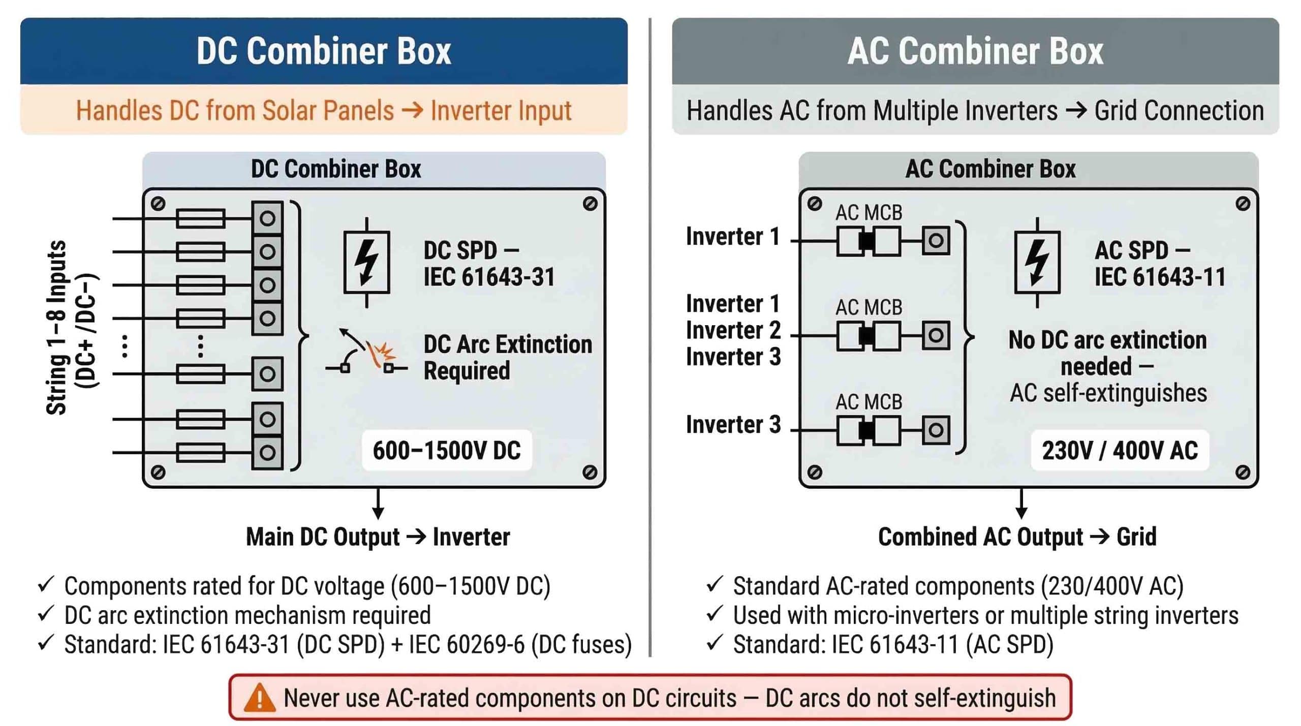
A DC combiner box and an AC combiner box are not interchangeable — using AC-rated components on the DC side of a PV system is a fire hazard because DC arcs do not self-extinguish the way AC arcs do at zero-crossings. The distinction between the two types is fundamental and non-negotiable from a safety standpoint.
4.1 Where Each Type Is Installed
A DC combiner box is installed on the DC side of the solar system — between the PV array strings and the inverter's DC input. It handles raw, unconverted solar energy at voltages from 600V DC (residential systems) up to 1500V DC (utility-scale systems). All components inside must be DC-rated at the system voltage.
An AC combiner box is installed on the AC side — after the inverter, aggregating the AC outputs of multiple inverters (common in large installations with multiple string inverters or micro-inverters) before connecting to the main AC distribution board or grid connection point. All components are standard AC-rated devices at 230V or 400V AC.
4.2 Why They Cannot Be Interchanged: The DC Arc Problem
The fundamental technical barrier is DC arc extinction. In AC circuits, the current passes through zero 100–120 times per second (at 50–60Hz). When an AC fault occurs, the arc that forms naturally extinguishes itself at each zero-crossing. AC circuit breakers and SPDs are designed around this characteristic.
In DC circuits, there is no zero-crossing. A DC arc, once ignited, is self-sustaining and will burn continuously until the circuit is physically interrupted or the source energy is exhausted. At 1000–1500V DC, a sustained arc carries enough energy to vaporise copper conductors, ignite enclosure materials, and cause catastrophic fire. An AC-rated circuit breaker used on a DC circuit cannot reliably interrupt the DC fault arc — its arc quenching chamber is simply not designed for it.
Never install AC-rated fuses, MCBs, or SPDs on the DC side of a PV system. All DC combiner box components must carry explicit DC voltage ratings at or above the system maximum open-circuit voltage, and DC SPDs must be certified to IEC 61643-31 (not IEC 61643-11).
| Parameter | DC Combiner Box | AC Combiner Box |
|---|---|---|
| Installation position | PV array → Inverter DC input | Inverter AC output → Grid |
| Operating voltage | 600–1500V DC | 230V / 400V AC |
| Overcurrent devices | DC PV fuses (IEC 60269-6) or DC MCBs | Standard AC MCBs |
| SPD standard | IEC 61643-31 (DC-specific) | IEC 61643-11 (AC standard) |
| Arc extinction | Active DC arc quenching required | Natural AC zero-crossing extinction |
| Used with | String inverters, central inverters | Micro-inverters, multiple string inverters |
| Interchangeable? | No — using AC components on DC circuits is a fire hazard | |
5. Do You Need a Solar Combiner Box? The 3-String Rule Explained
A PV combiner box becomes essential when your system has 3 or more PV strings connected in parallel to the same inverter MPPT input — this is the 3-String Rule, grounded in the fault behaviour of parallel-connected PV strings and mandated by IEC 60364-7-712.
When multiple strings are connected in parallel without individual string protection, a faulty string (shorted or heavily shaded) can draw reverse current from the healthy parallel strings. This back-fed current flows through the faulty string's cells and cables, causing localised overheating, accelerated degradation, and in severe cases, fire. The per-string fuses inside a combiner box prevent this by isolating the faulty string immediately upon fault detection.
For small systems with only 1 or 2 strings, modern string inverters with built-in MPPT inputs and integrated fuse holders can be connected directly — a combiner box is not required. However, once a third string is added in parallel, the fault current multiplication effect becomes significant enough that per-string protection via a combiner box is mandated by IEC 60364-7-712 and recommended by all major inverter manufacturers.
| System Configuration | Combiner Box Required? | Reasoning |
|---|---|---|
| 1–2 strings, modern inverter with built-in MPPT + fuse holders | Not required | Inverter internal protection sufficient; back-fed current risk minimal |
| 3+ strings in parallel to one MPPT input | Required | Back-fed fault current from parallel strings requires per-string fuse protection |
| Any system with long DC cable runs (>10m between array and inverter) | Required | DC SPD required at combiner box location; SPD must be within 10m of inverter or installed at both ends |
| Any installation with external LPS (lightning rod) | Required | Type 1+2 DC SPD required at LPZ boundary; best installed in dedicated combiner box |
| Ground-mounted arrays, commercial rooftop ≥15kW | Required | System complexity, maintenance requirements, and monitoring needs mandate centralised protection |
6. How to Choose a Solar Combiner Box: 5-Step Selection Guide
Choosing the correct solar combiner box requires matching five key parameters to the specific system design — string input count, maximum DC voltage, overcurrent protection type, DC SPD specifications, and enclosure rating. Undersizing any parameter risks equipment damage or safety failure; oversizing increases cost without benefit.
6.1 Step 1 — Determine Number of String Inputs Required
Count the number of PV strings that will connect to this combiner box. For systems with multiple inverter MPPT inputs, calculate strings per MPPT. Standard combiner box configurations are 1-in/1-out, 2-in/1-out, 3-in/1-out, 4-in/2-out, and 6-in/2-out. For larger systems, multiple combiner boxes are used — one per inverter or per inverter MPPT group.
6.2 Step 2 — Match Maximum DC Voltage
The dc combiner box maximum voltage rating must equal or exceed the PV string open-circuit voltage (Voc) at the coldest expected ambient temperature. As PV panel voltage increases with decreasing temperature, the maximum Voc is calculated as:
VOC max = VOC(STC) × [1 + |αVoc| × (25°C − Tmin)]
Example: String VOC(STC) = 400V, Tmin = −10°C, αVoc = −0.003/°C
VOC max = 400 × [1 + 0.003 × 35°C] = 400 × 1.105 = 442V → select 1000V DC combiner box
Standard ratings: 600V DC (small off-grid), 1000V DC (standard commercial), 1500V DC (utility-scale)
6.3 Step 3 — Select Overcurrent Protection Type: Fuse vs MCB
Two protection technologies are available for per-string protection in a dc combiner box:
- DC PV Fuses (fuse-equipped models): Lower cost, reliable one-time protection. Fuse cartridge must be replaced after a fault event. Preferred for fixed commercial and utility installations where faults are infrequent and maintenance access is planned. Fuse rating = 1.5–2× string Isc.
- DC MCBs (MCB-equipped models): Manually resettable after tripping. Preferred for residential systems or installations with frequent maintenance access. Must be specifically rated as DC MCBs per IEC/EN 60947-2 — standard AC MCBs cannot be substituted.
6.4 Step 4 — Verify DC SPD Specifications
All TrilPeak combiner boxes include a factory-installed Type 2 DC SPD rated Ucpv 1000V DC / Imax 40kA / IEC 61643-31. For systems with lightning protection zones requiring Type 1+2 protection (Iimp ≥ 12.5kA), a separate Type 1+2 DC SPD must be installed at the LPZ boundary — the combiner box Type 2 SPD remains as the second layer of protection.
6.5 Step 5 — Confirm Enclosure Rating and Dimensions
Verify the enclosure dimensions fit the available wall space and that the cable gland sizes match the installed cable cross-sections (typically 2.5–16mm² for both input and output cables).
7. Solar Combiner Box Wiring Diagram and Installation
Correct solar combiner box wiring determines both protection effectiveness and long-term system reliability — the critical rules are SPD lead length ≤0.5m, PE conductor ≥6mm², and output cable run ≤10m before a second DC SPD is required at the inverter. The following guidelines cover a standard 3-string installation using a fuse-based combiner box.
7.1 Step 1 — Mounting Location
Mount the combiner box as close to the PV array as possible to minimise DC cable runs, while ensuring accessibility for maintenance. For rooftop installations, mount at eave level or on a structural wall — not on the roof surface itself. Ensure the enclosure faces away from direct long-term sun exposure where possible to minimise thermal cycling effects on internal components.
7.2 Step 2 — Cable Entry and Sealing
Route all DC input cables (one DC+/DC− pair per string) through the designated cable glands at the top or sides of the enclosure. Tighten glands to the manufacturer's specified torque to maintain enclosure sealing. Use only PV-rated DC cables (rated 1000V DC or 1500V DC as applicable, UV-resistant jacket) for all connections inside and between combiner box and inverter.
7.3 Step 3 — String Fuse Connection
Connect each string DC+ cable to its corresponding fuse holder input terminal. Verify polarity before tightening — reversed polarity will place the fuse on the negative line, creating a protection gap. Fuse rating must be ≥ 1.5× string Isc and ≤ 2.4× string Isc per IEC 60364-7-712 Section 712.533.
7.4 Step 4 — DC SPD Connection: Critical Lead Length Requirement
The DC SPD is connected in parallel across the DC busbars (positive busbar to PE, and optionally negative busbar to PE in 3-mode configurations). The total length of the wiring from the SPD terminals to the busbar connection point — the "SPD lead length" — must be kept below 0.5 metres per IEC 61643-31. Longer leads introduce inductive impedance that adds additional voltage stress during a surge event, reducing the SPD's clamping effectiveness. For most DIN-rail mounted combiner box designs, this requirement is automatically met by the factory-installed SPD wiring.
7.5 Step 5 — PE Ground Connection
Connect the SPD PE terminal and the enclosure ground lug to the installation's equipotential bonding system using a minimum 6mm² copper conductor. The ground connection resistance must be ≤ 10Ω to the grounding electrode per IEC 62305. A high-resistance ground path dramatically reduces SPD effectiveness — the surge current will find an alternative path through the equipment being protected.
7.6 Step 6 — Output Cable to Inverter
Run the main DC+ and DC− output cables from the combiner box to the inverter DC input. Keep this cable run to ≤ 10 metres where possible. If the inverter is more than 10m from the combiner box, install a second Type 2 DC SPD at the inverter DC input terminals — the cable inductance over 10m generates enough additional voltage overshoot during a surge to justify the second protective stage. Use the same PV-rated 1000V/1500V DC cable specification.
Commissioning check: Before closing the enclosure and switching on, verify: (1) correct polarity on all string connections — use a DC multimeter to confirm DC+ and DC− polarity at each fuse holder input before connecting. (2) SPD status indicator shows green. (3) Isolator is in OFF position. (4) All cable glands are hand-tight plus ¼ turn to maintain enclosure sealing.
8. Solar Combiner Box Selection by System Size
The specification of a solar combiner box — and the number of combiner boxes required — varies significantly with system scale across three main PV installation categories: residential (≤15kW), commercial (15kW–1MW), and utility-scale (>1MW).

8.1 Residential Rooftop Solar (≤15kW)
Most residential systems with fewer than 3 strings per MPPT input connect directly to the inverter without a dedicated combiner box. For systems with 3 or more strings, or where DC cable runs exceed 10m, a compact combiner box is required. TrilPeak 2-in/1-out or 3-in/1-out fuse-equipped combiner box models are the standard residential specification: 2 or 3 string inputs, 1000V DC, DC PV fuses, Type 2 DC SPD (Imax 40kA), wall-mount, compact footprint.
8.2 Commercial Rooftop and Ground-Mount (15kW–1MW)
Commercial systems typically use one combiner box per inverter MPPT input, or one combiner box per sub-array. String count per combiner ranges from 4 to 16. For moderate lightning risk regions (flash density <2 flashes/km²/year), Type 2 DC SPDs inside the combiner box are sufficient. For higher-risk sites or any installation with external lightning protection, upgrade the combiner box SPD to Type 1+2, or install a separate Type 1+2 DC SPD upstream. TrilPeak 4-in/2-out, 6-in/2-out fuse-equipped or MCB-equipped combiner box models cover the commercial specification range.
8.3 Utility-Scale Ground-Mount (>1MW, 1500V DC)
Utility-scale systems require 1500V DC rated combiner boxes distributed across the solar field, each aggregating 16–32 strings. Key additional requirements for utility-scale: remote monitoring output (NO/NC signalling contact) from the SPD for SCADA integration, Type 1+2 DC SPDs at the main DC combiner level (Iimp ≥ 12.5kA, Ucpv 1500V), and full IEC 62305-3 three-layer lightning protection coordination. TrilPeak can supply custom-configured combiner boxes for utility-scale specifications — contact our engineering team for project-specific design support.
| Specification | Residential ≤15kW | Commercial 15kW–1MW | Utility Scale >1MW |
|---|---|---|---|
| Strings per combiner | 1–3 | 4–16 | 16–32 |
| DC Voltage | 600–1000V DC | 1000–1500V DC | 1500V DC |
| Overcurrent protection | DC PV fuses 16A/1000V | DC fuses or MCBs, 15–30A/1000–1500V | DC fuses 30A/1500V (IEC 60269-6) |
| DC SPD type | Type 2, Ucpv 1000V, Imax 40kA | Type 2 or Type 1+2 depending on lightning risk | Type 1+2, Iimp ≥12.5kA, Ucpv 1500V + remote signalling |
| Monitoring | SPD LED indicator | String monitoring recommended | SCADA-integrated monitoring mandatory |
| TrilPeak model | 2-in or 3-in/1-out fuse series | 4-in or 6-in/2-out fuse or MCB series | Custom — contact engineering |
9. Frequently Asked Questions: Solar Combiner Box
9.1 What is a solar combiner box and what does it do?
A solar combiner box (also called a PV combiner box or DC combiner box) is a weatherproof electrical enclosure installed between the PV array and the inverter. It collects the DC output cables from multiple solar panel strings, combines them onto a common busbar, and routes the combined DC power to the inverter. Beyond current aggregation, it houses per-string overcurrent protection (DC PV fuses or DC MCBs), a Type 2 DC SPD for surge protection rated to IEC 61643-31, a DC isolator switch for safe maintenance disconnection, and a PE ground bar — all in a single enclosure.
9.2 Do I need a solar combiner box for my PV system?
A solar combiner box is required when your system has 3 or more PV strings connected in parallel to the same inverter MPPT input — this is the 3-String Rule. For 1–2 strings with a modern inverter that has built-in MPPT inputs and fuse holders, a separate combiner box is not required. However, a combiner box is also required when DC cable runs exceed 10m (DC SPD must be installed close to the array), when the installation has external lightning protection, or when string-level monitoring is required for commercial system management.
9.3 What is the difference between a DC combiner box and an AC combiner box?
A DC combiner box is installed between the PV array and the inverter DC input — it handles DC power at 600–1500V DC and contains DC-rated components (DC PV fuses per IEC 60269-6, DC SPD per IEC 61643-31, DC isolator switch). An AC combiner box is installed after the inverter, aggregating AC outputs from multiple inverters before the grid connection — it uses standard AC-rated components at 230/400V AC. They are not interchangeable: DC arcs do not self-extinguish at zero-crossings the way AC arcs do, so AC-rated components will fail dangerously if used in DC circuits.
9.4 What components are inside a PV combiner box?
A standard solar combiner box contains: (1) DC PV fuse holders with fuse cartridges rated for PV DC applications per IEC 60269-6 — one per string input. (2) DC positive and negative busbars connecting all string outputs in parallel. (3) A Type 2 DC SPD rated to IEC 61643-31, connected between the busbars and the PE ground rail, to protect against lightning and switching surges. (4) A DC load-break isolator switch on the main output circuit for safe disconnection. (5) A PE ground busbar for equipotential bonding. (6) A weatherproof enclosure with cable glands. Higher-specification models also include DC MCBs instead of fuses, string monitoring modules, and SPD remote signalling contacts.
9.5 How do I choose the right solar combiner box for my system?
Select a solar combiner box by matching five parameters: (1) Number of string inputs — choose a model with the correct input count (2-in, 3-in, 4-in, 6-in, etc.). (2) DC voltage rating — must be ≥ the maximum string open-circuit voltage at the lowest expected temperature; standard ratings are 1000V DC or 1500V DC. (3) Overcurrent protection type — DC PV fuses for most fixed installations; DC MCBs for easier maintenance reset. (4) DC SPD specification — verify IEC 61643-31 certification, Ucpv matching system voltage, and Imax rating appropriate to lightning risk. (5) Enclosure dimensions — verify mounting space and cable gland compatibility with your cable cross-sections.
9.6 What does a solar combiner box wiring diagram show?
A solar combiner box wiring diagram shows how multiple PV strings connect through the combiner box to the inverter. The standard connection sequence per string is: String DC+ cable → DC PV fuse → Positive busbar → DC isolator → Inverter MPPT DC+ terminal. For the negative line: String DC− cable → Negative busbar → DC isolator → Inverter MPPT DC− terminal. The DC SPD is connected in parallel between the positive busbar and the PE ground rail. The PE ground bar connects to the system equipotential bonding with ≥6mm² copper. A critical installation rule: the SPD lead length from device terminals to busbar must be ≤0.5m per IEC 61643-31.
9.7 Can I use a combiner box for solar panels rated at 1500V DC?
Yes — combiner boxes rated for 1500V DC are available and are standard for utility-scale solar installations. All internal components must be specifically rated for 1500V DC: DC PV fuses rated 1500V DC per IEC 60269-6, DC SPD with Ucpv ≥ 1500V per IEC 61643-31, DC isolator switch rated ≥ 1500V DC, and busbars sized for the combined string current. Standard 1000V DC combiner boxes cannot be used in 1500V DC systems — operating components beyond their rated voltage is a critical safety violation.
9.8 How often should a solar combiner box be inspected?
Inspect solar combiner boxes at minimum once per year and after any known lightning event near the installation. During inspection: (1) Visually check SPD status indicator — green indicates operational; if indicator shows fault, replace SPD module immediately. (2) Check fuse holder LEDs (if fitted) for blown fuse indication. (3) Inspect cable glands for tightness and seal integrity. (4) Check terminal connections for signs of corrosion or loosening. (5) Verify enclosure door seals are intact. For commercial and utility-scale installations, quarterly inspection is recommended, with SPD status integrated into SCADA monitoring for continuous oversight.
9.9 Is a combiner box for solar panels the same as a junction box?
No — these are two completely different components. A solar junction box is the small sealed plastic enclosure on the back of each individual solar panel, housing the bypass diodes and MC4 connector leads. It is a panel-level component and is integral to the panel itself. A solar combiner box is a separate, system-level enclosure installed during system construction, combining the outputs of multiple strings. It is significantly larger, contains active protection devices (fuses, SPD, isolator switch), and is independently specified, installed, and maintained.
9.10 What standards apply to solar combiner boxes?
Solar combiner boxes and their internal components must comply with several standards: IEC 60364-7-712 governs the overall design and installation of PV power supply systems, including combiner box placement, overcurrent protection sizing, and isolation. IEC 60269-6 covers DC PV fuses for photovoltaic energy systems. IEC/EN 60947-2 covers DC MCBs for industrial use. IEC 61643-31 is the critical standard for DC surge protective devices in PV installations — all SPDs inside combiner boxes must carry IEC 61643-31 certification. IEC 62305-3 provides the framework for coordinated lightning and surge protection. For US installations, NEC Article 690 covers PV system electrical requirements including combiner box specifications.
Related Resources & Standards
Need a PV Combiner Box for Your Solar Project?
TrilPeak supplies IEC 61643-31 certified DC SPD-equipped combiner boxes for residential, commercial, and utility-scale installations — with factory-direct pricing and engineering support.