Single Phase vs Three Phase Power: Engineering Selection Guide
Single phase vs three phase power is the most fundamental classification in AC distribution. Single phase delivers one AC waveform — nominally 230 V line-to-neutral (IEC) or 120 V (North America). Three phase delivers three waveforms offset by 120°, nominally 400 V line-to-line (IEC) or 208/480 V (North America). For the same delivered power, equal voltage, and equal power factor, three phase draws approximately 1/√3 ≈ 57.7% of the current per conductor that single phase would require — the core reason three phase is the default for motors above 2.2 kW, industrial panels, and high-density facilities.
Quick Answer: Single Phase vs Three Phase
Single phase (1φ): One AC waveform — nominally 230 V L–N (IEC) or 120 V (NA). Standard for residential loads, lighting, and equipment under 15 kW.
Three phase (3φ): Three waveforms offset by 120°, near-constant power. Nominally 400 V L–L (IEC) or 208/480 V (NA). Standard for motors above 2.2 kW, industrial panels, and data centres.
Core engineering difference: At equal power, equal line voltage, and equal power factor, three phase draws less current per conductor than single phase — smaller cables, lower losses, better distribution density.
1. Single Phase vs Three Phase: 7 Key Differences at a Glance
The seven dimensions below are the most-asked single phase vs three phase comparison points among engineers, electricians, and students. Use this table as a quick reference before the detailed sections that follow.
| Dimension | Single Phase (1φ) | Three Phase (3φ) |
|---|---|---|
| Service voltages | IEC: 230 V L–N (nominal) · NA: 120 V / 120/240 V split-phase | IEC: 400 V L–L (nominal, 415 V legacy) · NA: 120/208 V, 277/480 V |
| Conductors | 1 live (phase) + 1 neutral + PE | 3 live conductors; neutral available in wye (+PE), absent in delta |
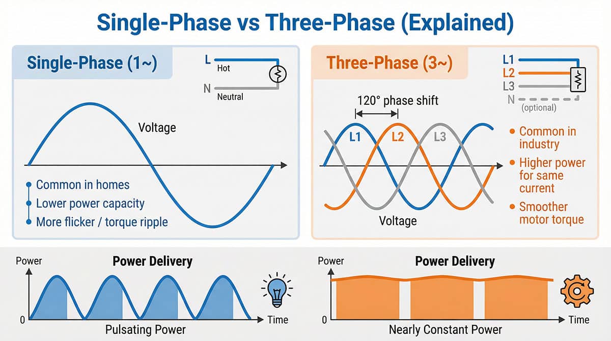
| Power delivery | Pulsating — drops to zero twice per cycle | Near-constant — three waveforms overlap at 120° intervals |
| Current per conductor (equal power, voltage & PF) | Higher — larger cables, greater voltage drop | Lower by factor √3 ≈ 1.732 — smaller cables, less loss |
| Motor suitability | Up to ~2.2–3.7 kW; requires starting capacitor | 2.2 kW and above; self-starting, consistent torque, VFD (Variable Frequency Drive)-ready |
| Typical applications | Residential, lighting, small HVAC, light commercial loads | Industrial motors, drives, compressors, data centres, large facilities |
| Surge protection (IEC 61643-11) | Type 2 SPD (Surge Protective Device), commonly 1+1 or 1+0 mode depending on earthing system | Type 2 SPD, commonly 3+0, 3+1, or 4-pole mode depending on earthing system |
2. What Is Three Phase Power? Definition, Parameters & How It Works
Three phase power is an AC electrical system using three live conductors carrying the same nominal voltage and frequency, each shifted 120° out of phase — producing near-constant power delivery that single phase cannot replicate. Three phase is not simply three single-phase supplies stacked together. The conductors share a common return path (neutral in wye systems) and the three-waveform relationship creates properties — constant torque in motors, lower conductor current for equal power — that three independent single-phase supplies cannot achieve.
2.1 What Is Three Phase Electricity? Key Parameters
| Parameter | IEC / European | North America |
|---|---|---|
| Line-to-line voltage (L–L) | 400 V nominal (415 V legacy) | 208 V (commercial) / 480 V (industrial) |
| Line-to-neutral voltage (L–N) | 230 V nominal | 120 V (208 V wye) / 277 V (480 V wye) |
| Frequency | 50 Hz | 60 Hz |
| Phase shift | 120° between each conductor pair | 120° between each conductor pair |
| Standard conductor count (wye) | 3 live + neutral + PE (5-wire) | 3 live + neutral + PE (5-wire) |
These are nominal (standard) values per IEC 60038, not guaranteed instantaneous readings. Actual supply voltage varies within the tolerance band set by local grid codes and power quality regulations.
2.2 Three Phase Supply: Wye (Star) vs Delta
Three phase power is distributed in one of two configurations — wye (star) or delta — and the choice determines whether a neutral conductor is available for single-phase branch circuits.
- Wye (Star, Y) — the most common in commercial and industrial buildings: All three phase conductors connect to a common neutral point. This gives you both L–N voltage (230 V IEC, 120 V or 277 V NA) for single-phase circuits and L–L voltage (400 V IEC, 208 V or 480 V NA) for three-phase loads from the same supply.
- Delta (Δ) — used in some industrial feeders: Phases are connected in a triangle with no common neutral point. Delta is a 3-wire system often used for purely three-phase industrial loads such as large motor feeders. Without a neutral, L–N branch circuits cannot be run from a delta supply without a transformer.
Many engineers assume three phase always means 400 V. In a wye-connected system, you have both 230 V L–N and 400 V L–L available from the same service — they come from the same three-phase transformer. Single-phase loads (230 V lighting, general sockets) are simply connected between one phase conductor and neutral.
3. What Is Single Phase Power? Definition & How It Works
Single phase power delivers a single sinusoidal AC waveform via one live conductor and one neutral return — the simplest and most widely available electrical supply type for residential and light commercial use. Because the waveform crosses zero twice per cycle, power delivery briefly drops to zero at each crossing. For resistive loads like lighting or heating, this is imperceptible. For rotating motors, the zero-crossing means the magnetic field collapses and rebuilds twice per cycle — which is why single phase motors typically require a starting capacitor or auxiliary winding to generate an initial rotating field.
In IEC markets, single phase electricity runs at a nominal 230 V between the live conductor and neutral (L–N). In North America, the nominal standard is 120 V L–N. The single-phase supply to a residential property typically comes from a single winding of a distribution transformer — it is one phase of the utility's three-phase grid, tapped off for lower-demand customers.
3.1 Split Phase vs Single Phase: The North American Distinction
In the United States and Canada, residential service is often described as split phase rather than simply single phase. Split phase uses a center-tapped single transformer winding that provides 120 V on each half and 240 V across the full secondary. Despite having two hot wires, split phase is not two-phase power — it is one single-phase transformer winding with a midpoint neutral.
Split phase vs three phase — the key test: If you measure between the two "hot" conductors of a split-phase supply and get 240 V, you are on a single-phase (split-phase) system. If you measure between any two of the three conductors and get 208 V or 480 V, you are on a three-phase system.
4. Why Use Three Phase Instead of Single Phase? 4 Engineering Reasons
Three phase power solves four engineering problems that single phase cannot address at scale: constant power delivery, lower current per conductor at equal power, self-starting motors, and higher power density for the same wiring infrastructure. These advantages grow with load — modest for appliances under 2 kW, decisive for industrial motors and distribution above 10 kW.
4.1 Near-Constant Power Delivery — No Zero-Crossings
A single phase waveform crosses zero twice per AC cycle — 100 times per second at 50 Hz. At each zero crossing, instantaneous power delivery drops to zero. For rotating motors, the twice-per-cycle power interruption creates torque ripple — uneven rotational force that causes vibration, reduces efficiency, and shortens bearing life in larger machines.
Three phase power eliminates this problem. With three waveforms offset by 120°, the combined instantaneous power from all three phases remains virtually constant. This is why industrial motors above a few kilowatts are typically designed for three phase supply.
4.2 Lower Current Per Conductor at Equal Power — Reducing Infrastructure Cost
This comparison holds specifically when comparing equal delivered power, equal line voltage, and equal power factor between the two systems. The ratio does not apply when comparing different voltage levels or different power factors.
Under these equal conditions, three phase electricity requires approximately 1/√3 ≈ 57.7% of the current per conductor that single phase would require. In practice, at equal delivered power and equal voltage, this typically means:
- Smaller conductor cross-sections — lower cable procurement cost
- Lower I²R losses — better energy efficiency on long feeder runs
- Less voltage drop — easier to maintain regulation over distance
- Smaller breakers, busbars, and switchgear — reduced panel footprint
This is captured in the three phase power formula: P = √3 × VL-L × I × PF. The √3 factor reflects the relationship between three-conductor delivery and equivalent single-conductor current at the same power and voltage.
4.3 Self-Starting Motors Without Capacitors
A single phase induction motor does not inherently self-start. Because a single sinusoidal current through a coil produces an alternating (not rotating) magnetic field, an additional mechanism is typically required to create the initial torque — most commonly a starting capacitor or a shaded pole design.
Three phase motors generate a rotating magnetic field directly from the 120° phase relationship between the three currents, and are generally self-starting without a capacitor, with direction reversible by swapping any two of the three supply conductors. Note that some three phase motors still use additional starting or control accessories — such as soft starters or VFDs — to manage large inertial loads or to improve starting characteristics, even though a capacitor is not required for the rotating field itself.
4.4 Higher Power Density for the Same Wiring Infrastructure
Three phase wiring can carry substantially more power than single phase wiring of comparable conductor count, which is a primary reason utility grids operate on three phase for bulk energy transmission. For industrial facilities, data centres, and large commercial buildings, three phase distribution panels can serve more load than equivalent single-phase infrastructure without proportionally increasing cable routing or panel footprint.
5. Single Phase vs Three Phase Voltage: IEC and North American Systems
In IEC markets, single phase is nominally 230 V L–N and three phase is nominally 400 V L–L — both from the same wye supply. In North America, single phase residential is 120/240 V split-phase; three phase commercial is 120/208 V and industrial is 277/480 V. These are standard nominal values per IEC 60038 and North American utility practice — actual supply voltage varies within local tolerance bands.
5.1 Is 3 Phase Always 400V? IEC Markets Explained
No — 400 V is the nominal three-phase line-to-line value in IEC markets, but it is not universal even within IEC-aligned countries, and it is not the three-phase voltage in North America. In most IEC-compliant markets (Europe, Australia, most of Asia, Middle East, Africa), the nominal voltages defined by IEC 60038 are:
- Single phase electricity: 230 V line-to-neutral (L–N) nominal
- Three phase electricity: 400 V line-to-line (L–L) nominal
- The relationship: 400 V ÷ √3 = 230.9 V — the 230 V and 400 V figures come from the same three-phase wye supply. Older UK documentation referenced 415 V L–L and 240 V L–N; the nominal values changed under European harmonisation, though equipment remains compatible.
5.2 North American Systems: 120/208 V and 277/480 V
- 120/208 V wye: Common for commercial buildings — 120 V L–N for receptacles and lighting, 208 V L–L for small three-phase equipment. 208 V single-phase (taken from two legs of the wye) is not the same as 240 V split-phase residential service.
- 277/480 V wye: Common for industrial facilities — 277 V L–N for lighting ballasts, 480 V L–L for large motors and drives.
5.3 Three Phase Power Formula: P = √3 × V × I × PF
The three-phase power formula is used for conductor sizing, transformer selection, and SPD specification:
P (kW) = √3 × VL-L × I × PF ÷ 1000
Where: VL-L = line-to-line voltage · I = current per conductor (amps) · PF = power factor (commonly 0.85 for general industrial loads, 1.0 for resistive loads) · √3 ≈ 1.732
Example: A 400 V three-phase motor drawing 100 A at PF 0.85: P = 1.732 × 400 × 100 × 0.85 ÷ 1000 = 58.9 kW
6. Single Phase vs Three Phase Wiring: Conductors, Configurations & Identification
Single phase wiring uses 1 live conductor + 1 neutral + PE. Three phase wiring uses 3 live conductors plus a neutral (wye) or no neutral (delta), plus PE. Getting the configuration right at design stage prevents the most common commissioning problems — overloaded legs, excessive neutral current, and protection miscoordination.
6.1 Single Phase Wiring
Standard single phase wiring uses two current-carrying conductors: one live conductor (phase, hot) and one neutral return, plus a separate protective earth (PE/ground). In most installations this is a 3-core cable (L + N + PE). Cable sizing follows the load current directly — for a 10 kW single-phase load at 230 V, the current is approximately 43 A (at PF 1.0).
6.2 Three Phase Wiring — Wye (Star) 4-Wire System
The most common three phase wiring configuration in commercial and industrial buildings is the 4-wire wye system: three live conductors (L1, L2, L3) plus a neutral conductor, all referenced to protective earth. Standard cable is 5-core (L1 + L2 + L3 + N + PE). The neutral carries the vector sum of unbalanced currents — in a perfectly balanced three-phase load it is theoretically zero, but real installations always have some imbalance.
Unbalanced panel design — where one leg carries significantly more load than the others — increases neutral current, reduces the effectiveness of three-phase protection devices, and causes premature neutral conductor heating. Circuit allocation across the three phases should be balanced at panel design stage.
6.3 Three Phase Wiring — Delta 3-Wire System
Delta uses three live conductors with no neutral, suited to purely three-phase loads (large motors, some industrial feeders) where no L–N branch circuits are required. Delta configurations are less common in new building installations because modern facilities need single-phase circuits for lighting and outlets.
6.4 How to Identify Single Phase vs Three Phase Supply on Site
| Check | Single Phase Result | Three Phase Result |
|---|---|---|
| 1. Main breaker pole count | 1-pole or 2-pole (split phase) | 3-pole breaker |
| 2. Voltage measurement (hot to hot) | 240 V (split phase NA) or 0 V (single phase IEC) between the two conductors | 208 V, 400 V, or 480 V between any two live conductors |
| 3. Conductor count at service entry | 2 current-carrying conductors (+ PE) | 3 current-carrying conductors (+ optional neutral + PE) |
| 4. Equipment nameplate | "1φ", "1PH", "Single Phase", or "120 V" / "230 V" | "3φ", "3PH", "Three Phase", "208 V", "400 V", or "480 V" |
Do not guess based on wire count alone. Some split-phase residential panels have 4 conductors visible at the panel (2 hot + neutral + ground), which can be confused with three-phase. Always measure voltage between conductors before specifying protection devices or SPDs.
7. Single Phase vs Three Phase Motor: Selection, Starting & VFD Applications
The single phase motor vs three phase motor selection affects starting method, efficiency, maintenance requirements, and drive compatibility — motors are often the deciding factor in the single phase vs three phase power decision.
7.1 Why Three Phase Motors Generally Don't Need Starting Capacitors
In a three phase motor, the 120° phase shift between L1, L2, and L3 currents directly produces a rotating magnetic field in the stator windings, inducing rotor current and generating torque without an external starting aid in most standard designs. The motor is typically self-starting in both directions, with direction reversed by swapping any two supply conductors.
A single phase motor has only one set of stator windings. When energised with a single-phase supply, the magnetic field alternates rather than rotating — producing no net starting torque. Single phase motors typically use a starting capacitor in series with an auxiliary winding, a permanent run capacitor, or a shaded pole arrangement. These add cost, reduce reliability, and generally limit motor power ratings to approximately 2.2–3.7 kW in practical designs.
7.2 VFD Applications: Three Phase Is the Natural Choice
Variable Frequency Drives (VFDs) are the dominant motor control method for pumps, fans, compressors, and conveyors in industrial and commercial facilities. Three phase motors pair naturally with VFDs — the drive synthesises three-phase output at variable frequency and amplitude. Single phase motors can technically be driven by VFDs, but the capacitor-based starting circuits are generally incompatible with VFD output.
For installations where VFD control is anticipated, three-phase supply and three-phase motors should be treated as the baseline. Three-phase drive panels require coordinated surge protection — VFDs generate high-frequency switching transients that couple back onto the supply, and lightning or grid switching surges can damage drive input stages. A three-phase surge protector rated to IEC 61643-11 should be installed at the panel feeding the drives.
7.3 When Single Phase Motors Still Make Sense
Single phase motors remain practical for portable tools and appliances where three-phase supply is unavailable, small HVAC units and domestic appliances, and agricultural or remote site equipment where the service is single-phase only. For loads below approximately 750 W, the efficiency and cost differences between single and three phase become marginal.
8. Single Phase vs Three Phase Surge Protection (SPD) Requirements
Both single phase and three phase power systems require surge protective devices per IEC 61643-11 — the device performance and test requirements are defined by the standard, while the specific pole configuration is a common engineering practice determined by the earthing system, not a value fixed by IEC 61643-11 itself.
8.1 Single Phase SPD Selection (230 V IEC / 120 V North America)
For a single-phase 230 V supply (IEC), a Type 2 SPD in 1+1 mode is a common choice for TT and TN-S earthing systems. The notation 1+1 means one varistor element between L and PE, and one between N and PE — covering both surge paths in a 3-wire single-phase circuit. Typical parameters used in practice:
- Maximum continuous voltage (Uc): commonly ≥ 255 V for nominal 230 V systems (approximately 1.1 × 230 V), though the exact required value depends on system tolerance, earthing arrangement, and the specific protection path — never select Uc = 230 V, as this leaves no margin for temporary overvoltages
- Nominal discharge current (In): commonly ≥ 20 kA (8/20 µs) at distribution panel level for industrial applications
- TN-C earthing (PEN conductor): commonly uses 1+0 mode — N and PE are the same conductor, so a separate N–PE varistor is not applicable
- North America 120 V: Uc commonly ≥ 150 V; split-phase 240 V across both hots commonly requires Uc ≥ 300 V
8.2 Three Phase SPD Selection (400 V / 480 V / 690 V)
Three phase SPD pole configuration is commonly selected based on the earthing system. A three-phase building with separate N and PE conductors (TN-S or TT) commonly uses a 4-pole SPD covering phase-to-earth and neutral-to-earth paths. Using a 3-pole SPD (more typical for TN-C or delta 3-wire systems) in a TN-S building can leave the neutral-to-earth path unprotected if the SPD configuration does not account for the separate neutral.
A common error in practice: installing a 3-pole (3+0) SPD in a building with separate N and PE conductors without verifying that the neutral path is also protected. Surges entering via an unprotected neutral can bypass the SPD entirely. Always verify your earthing system and confirm the SPD's protection paths against the manufacturer's wiring diagram before specifying pole count.
| Earthing System | Single Phase Config (common practice) | Three Phase Config (common practice) | Poles |
|---|---|---|---|
| TN-S (separate N + PE) | 1+1 (L–PE + N–PE) | 3+1 (L1/L2/L3–PE + N–PE) | 2P / 4P |
| TN-C (combined PEN) | 1+0 (L–PE only) | 3+0 (L1/L2/L3–PE only) | 1P / 3P |
| TT (local earth electrode) | 1+1 (L–PE + N–PE) | 3+1 or 4-pole (depending on manufacturer design) | 2P / 4P |
| TN-C-S (UK PME) | 1+1 (after split point) | 3+1 (after split point) | 2P / 4P |
These pole configurations reflect common engineering practice for each earthing system, not a fixed requirement specified directly by IEC 61643-11. IEC 61643-11 defines SPD performance, classification, and test methods; the specific wiring topology must be confirmed against IEC 60364, the system earthing arrangement, and the manufacturer's connection diagram for the actual installation.
9. Which Should You Choose? Single Phase vs Three Phase Selection Guide
The right single phase vs three phase power choice comes down to four factors: your load profile, the available site service, future expansion requirements, and equipment compatibility.
9.1 For OEM Equipment Designers
- Choose single phase when the target market is residential or light commercial, load is below 15 kW, and international compatibility is a priority.
- Choose three phase when the equipment includes motors above 2.2 kW, VFDs, compressors, or high-density loads.
9.2 For Panel Builders
- Single-phase panels are appropriate for small residential distributions, temporary power, and low-demand retail or light commercial installations.
- Three-phase panels require careful attention to load balancing across L1, L2, and L3. Confirm the earthing system (TT/TN-S/TN-C) early — it affects SPD configuration, RCD (Residual Current Device) selection, and neutral conductor sizing.
9.3 For EPC Contractors and Distributors
- Confirm the on-site voltage system early — the single phase vs three phase service configuration determines transformer sizing, busbar rating, breaker voltage ratings, and SPD Uc values.
- If the facility expects to add motors, EV charging, or process equipment within three to five years, the cost of upgrading to three-phase service now is generally lower than retrofitting later.
10. Conclusion: Single Phase vs Three Phase — The Decision That Shapes Your Entire System
The single phase vs three phase power decision shapes conductor sizing, motor selection, drive compatibility, protection strategy, and the long-term capacity of the entire electrical installation. Getting it right from the specification stage avoids one of the most expensive electrical retrofits in any facility: replacing single-phase infrastructure with three-phase after the building is complete.
- Single phase is the right choice for residential, light commercial, and portable equipment where loads stay below 15 kW and three-phase service is unavailable or uneconomical
- Three phase is the right choice for any installation with motors above 2.2 kW, drive-based control systems, high-density industrial loads, or significant future load growth
- Surge protection is required on both — single phase commonly uses a 230 V-rated Type 2 SPD per IEC 61643-11; three phase commonly uses a 400 V-rated Type 2 SPD in a pole configuration matched to the earthing system
- Always measure before specifying — supply voltage, earthing system type, and existing neutral configuration all affect equipment and protection device selection
11. Frequently Asked Questions: Single Phase vs Three Phase Power
11.1 What is the difference between single phase and three phase power?
Single phase power uses one live conductor and a neutral return to deliver AC electricity — the voltage waveform rises and falls in a single sinusoid, touching zero twice per cycle. Three phase power uses three live conductors, each carrying the same nominal voltage but shifted 120° apart. The three-waveform overlap means instantaneous power delivery is near-constant, and at equal delivered power, voltage, and power factor, each conductor carries less current than the equivalent single-phase circuit. Three phase is therefore the standard for motors, industrial loads, and high-density distribution where cable efficiency and motor starting performance matter.
11.2 What is three phase power and how does it work?
Three phase power is an AC electrical system where three live conductors carry identical sinusoidal voltages at the same frequency, each shifted 120° in phase. In an IEC 230/400 V system, each conductor is nominally 230 V line-to-neutral; the conductors are 400 V apart line-to-line. As one waveform descends toward zero, the other two are still at positive values — so the combined power delivery never drops to zero. This is why three phase motors generally run smoothly without starting capacitors and why three phase transmission is more efficient than single phase for delivering large amounts of power over the same conductor cross-section.
11.3 Why does three phase electricity exist? Why not just use single phase everywhere?
Three phase electricity solves problems that single phase cannot address efficiently at scale. Constant power delivery — three offset waveforms maintain continuous delivery; single phase dips to zero twice per cycle. Lower conductor current at equal power, equal voltage, and equal power factor — three phase draws approximately 1/√3 ≈ 57.7% of the current single phase would require, meaning smaller cables and lower losses under those equal conditions. Self-starting motors — the 120° phase relationship creates a rotating magnetic field directly; single phase generally needs capacitors to start. Transmission efficiency — three phase can carry substantially more power using only three conductors. These advantages grow with load: modest for appliances under 2 kW, decisive for industrial motors and distribution above 10 kW.
11.4 What does single phase vs three phase electricity mean for voltage?
In IEC markets, single phase electricity is nominally 230 V line-to-neutral. Three phase electricity from the same supply is nominally 400 V line-to-line, because 400 V ÷ √3 = 230.9 V — the two voltages come from the same transformer. In North America: single phase residential is typically 120/240 V split-phase; three phase commercial service is 120/208 V wye, and industrial service is 277/480 V wye. The key point is that 230 V and 400 V are not two different supplies — they are two ways of measuring voltage on the same three-phase wye distribution system.
11.5 What is the difference between split phase and three phase?
Split phase (North American residential) is a single-phase system using a center-tapped transformer secondary: two hot wires at 120 V each to neutral, 240 V between the two hots. Despite having two hot conductors, it is one transformer winding — not two phases. Three phase uses three separate windings shifted 120° apart, provides 208 V or 480 V between hot conductors, and can power three-phase motors without the starting equipment single-phase motors typically require. The two systems are fundamentally different and require different protection devices, breaker configurations, and equipment specifications.
11.6 What is the difference between single phase and three phase motors?
The key difference is starting behaviour. A three phase motor creates a rotating magnetic field directly from the 120° phase relationship between L1, L2, and L3 — it is generally self-starting in both directions and scales efficiently to high power ratings without a starting capacitor. A single phase motor only creates an alternating (not rotating) magnetic field and typically needs a starting capacitor or auxiliary winding to generate initial torque. Single phase motors are generally limited to approximately 2.2–3.7 kW; above this range, three phase is the practical option. For VFD-controlled applications, three phase motors are strongly preferred, as single-phase motor starting circuits are generally incompatible with VFD switching waveforms.
11.7 Which is better — single phase or 3 phase power?
Neither is universally better — the decision depends on load size, site constraints, and application. Three phase power is generally preferred for motors above 2.2 kW, industrial facilities, data centres, VFD applications, and installations where distribution efficiency and future expansion matter. Single phase power is the practical choice for residential properties, small commercial spaces, portable equipment, and sites where three-phase service is unavailable or the upgrade cost exceeds the long-term benefit.
11.8 How do you calculate 3 phase power?
Use the formula: P (watts) = √3 × VL-L × I × PF, where √3 ≈ 1.732, VL-L is the line-to-line voltage, I is the current per conductor in amps, and PF is the power factor. A common estimate uses PF = 0.85 for general industrial loads or PF = 1.0 for resistive loads. Example: at 400 V three phase with 50 A per conductor and PF 0.85: P = 1.732 × 400 × 50 × 0.85 = 29,444 W ≈ 29.4 kW.
11.9 How do you identify single phase vs 3 phase supply on site?
Four checks: count the main breaker poles — 1 or 2 pole means single phase (or split phase); 3-pole means three phase. Measure voltage between hot conductors — single phase/split phase gives 240 V (NA) or ~0 V (IEC single phase, only one hot); three phase gives 208 V, 400 V, or 480 V between any two hots. Count current-carrying conductors at the service entry — 2 means single phase, 3 means three phase. Check equipment nameplates for 1φ/1PH vs 3φ/3PH markings. Always measure before specifying SPDs, since the earthing system type and voltage determine the appropriate protection device configuration.
11.10 Do single phase and three phase systems need surge protection (SPDs)?
Yes — both single phase and three phase electrical systems require surge protection. Both are vulnerable to transient overvoltages from lightning, grid switching, and nearby high-inductive load switching. IEC 61643-11 defines performance and test requirements for SPDs used on both supply types. For single phase: a Type 2 SPD commonly with Uc ≥ 255 V in a 1+1 or 1+0 configuration, depending on earthing system. For three phase: a Type 2 SPD commonly with Uc ≥ 255 V per mode in a 3+0, 3+1, or 4-pole configuration matched to the earthing system. Selecting the wrong configuration — for example, a 1-pole SPD on a three-phase supply — can leave phases unprotected. See the TrilPeak SPD type comparison guide for full selection criteria.
Related Resources & Standards
Need IEC 61643-11 Certified SPDs for Single Phase or Three Phase Systems?
TrilPeak supplies Type 2 SPDs for all earthing systems (TN-S, TN-C, TT) in single phase and three phase configurations. CE certified · IEC 61643-11 · engineering reply within 24h.