
Grid-Tied vs Off-Grid Inverter: Key Technical Differences for Solar Engineers
Quick Answer
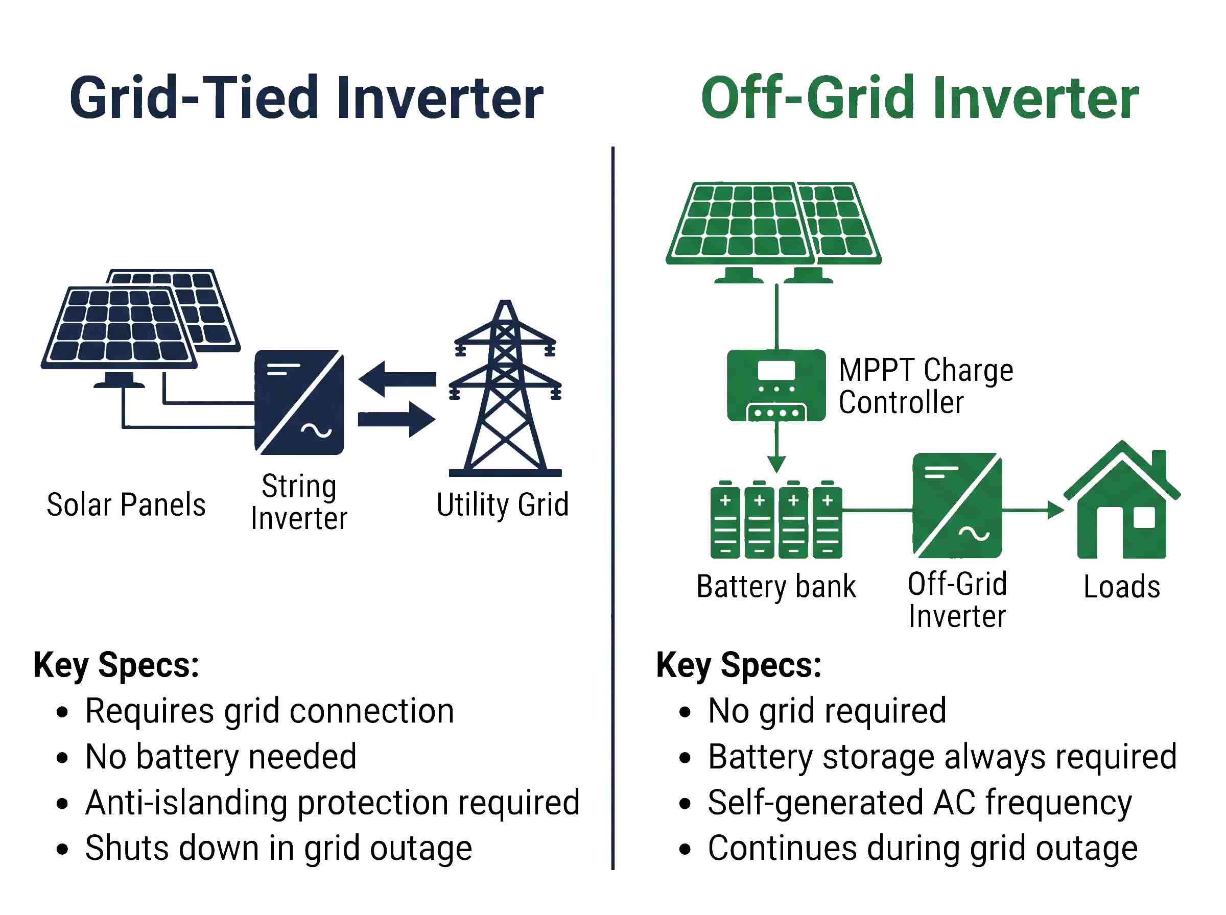
Grid-tied inverter: Synchronises DC-to-AC conversion with the utility grid frequency and voltage. Requires continuous grid connection to operate. No battery storage required. Anti-islanding protection is mandatory. Surge threat: grid-side switching transients plus array-side lightning induction.
Off-grid inverter: Operates independently from the utility grid. Generates its own AC frequency reference internally. Always paired with battery storage. No anti-islanding required. Surge threat: battery-side DC transients plus array-side lightning induction — different protection configuration required.
SPD implication: Both systems require DC-side surge protection (IEC 61643-31). Grid-tied systems additionally require AC-side SPDs at the grid connection point (IEC 61643-11). Off-grid systems require DC SPDs at both the PV array side and the battery bank side.
The choice between a grid-tied and off-grid inverter is not just a project design decision — it directly determines the surge protection configuration required for the entire solar installation. Each inverter type operates under a different set of electrical conditions, faces a different surge threat profile, and requires a different SPD specification. This guide covers the technical differences between grid-tied and off-grid inverters from the perspective of EPC contractors, system integrators, and electrical engineers specifying protection equipment under IEC/EN standards.
1. What Is a Grid-Tied Inverter?
A grid-tied inverter — also called a grid-connected inverter or on-grid inverter — is a power electronics device that converts DC electricity from a PV array into AC electricity synchronised to the utility grid. Synchronisation means the inverter continuously monitors the grid's voltage, frequency, and phase angle, and matches its own AC output to these parameters in real time.
This synchronisation function is the defining technical characteristic of a grid-tied inverter. It is what allows the inverter to inject power into the grid rather than simply consume it. When the PV array produces more energy than the connected loads require, the surplus flows back to the grid — a process called net metering or feed-in.
1.1 How a Grid-Tied Inverter Works
The conversion process in a grid-tied inverter involves three stages. First, the MPPT (Maximum Power Point Tracking) stage continuously adjusts the DC operating voltage to extract maximum power from the PV array regardless of irradiance and temperature conditions. Second, the DC-AC conversion stage uses high-frequency IGBT switching (typically 10–20 kHz) to generate a sinusoidal AC waveform. Third, the grid synchronisation stage uses a Phase-Locked Loop (PLL) circuit to lock the inverter's output frequency and phase to the grid reference, ensuring seamless power injection.
Grid-tied inverters include built-in protection functions required by grid connection standards: over/under voltage protection, over/under frequency protection, and critically — anti-islanding protection. Anti-islanding is the function that disconnects the inverter from the grid if the utility supply fails. Without it, the inverter would continue energising the grid cables after a grid outage, creating an electrocution hazard for utility workers.
1.2 Types of Grid-Tied Inverter
- String inverter: Connects to one or more series strings of PV modules. Most common type for C&I and utility-scale installations. Power range: 3 kW–250 kW per unit.
- Central inverter: A single large inverter serving an entire PV array section via a DC combiner box. Used in utility-scale plants. Power range: 500 kW–5 MW per unit.
- Microinverter: One inverter per panel, converting DC to AC at the module level. Used in residential and small commercial systems. Power range: 200–400 W per unit.
- Power optimizer + string inverter: Module-level DC optimizers feed a central string inverter. Combines module-level MPPT with string-level inversion.
2. What Is an Off-Grid Inverter?
An off-grid inverter — also called a stand-alone inverter — converts DC electricity from a battery bank (charged by PV panels, a generator, or both) into AC electricity for local loads. Unlike a grid-tied inverter, an off-grid inverter does not synchronise to an external grid reference. Instead, it generates its own AC voltage and frequency internally, acting as the sole power source for the connected loads.
Off-grid inverters are always paired with battery storage. The battery bank serves two functions: it stores energy from the PV array during periods of high solar production for use when generation is insufficient, and it provides the stable DC voltage source the inverter requires to generate a clean AC output.
2.1 How an Off-Grid Inverter Works
An off-grid system operates as a closed-loop power island. PV panels charge the battery bank through a charge controller (MPPT or PWM). The off-grid inverter draws DC power from the battery and converts it to AC at the rated output voltage and frequency — typically 230 V / 50 Hz for IEC markets. The inverter's internal oscillator sets the frequency reference; there is no external grid to synchronise with.
Because the off-grid inverter is the sole AC source, it must be sized to handle the full peak load of all connected equipment simultaneously — including motor starting inrush currents, which can reach 5–7× the running current. Undersizing an off-grid inverter for peak load is one of the most common specification errors in off-grid system design.
2.2 Types of Off-Grid Inverter
- Pure sine wave inverter: Generates a true sinusoidal AC output. Required for sensitive electronics, variable-frequency drives, and most modern appliances. Standard specification for all professional off-grid installations.
- Modified sine wave inverter: Generates a stepped approximation of a sine wave. Lower cost but unsuitable for sensitive electronics, motors with tight tolerance requirements, or medical equipment.
- Hybrid inverter: Combines grid-tied and off-grid functions in a single unit — can synchronise with the grid when available and switch to battery/island mode when the grid fails. Increasingly common in C&I BESS applications.
3. Grid-Tied vs Off-Grid Inverter: 7 Key Technical Differences
| # | Parameter | Grid-Tied Inverter | Off-Grid Inverter |
|---|---|---|---|
| 1 | Grid connection | Required — cannot operate without grid reference | Not required — operates independently |
| 2 | AC frequency reference | External (utility grid via PLL synchronisation) | Internal (self-generated oscillator) |
| 3 | Battery storage | Not required (optional in hybrid variants) | Always required |
| 4 | Anti-islanding protection | Mandatory per IEC 62116 / grid connection codes | Not applicable — no grid connection |
| 5 | Behaviour during grid outage | Shuts down immediately — cannot supply loads | Continues operating from battery |
| 6 | DC input source | PV array directly | Battery bank (charged by PV via charge controller) |
| 7 | Typical DC voltage range | 200–1,500 V DC (PV string voltage) | 12–120 V DC (battery bank voltage) |
4. How Inverter Type Affects SPD Selection
This is the section most relevant to EPC contractors and system integrators specifying surge protection. The grid-tied vs off-grid distinction creates fundamentally different surge threat profiles at different points in the system — and requires different SPD configurations in response.
4.1 Surge Threats in Grid-Tied Systems
A grid-tied solar installation faces surge threats from two independent directions simultaneously.
DC side (PV array to inverter input): Lightning striking within 1–2 km of the PV array induces transient overvoltages of several kilovolts on the DC string cables. These transients travel from the array through the combiner box toward the inverter's DC input. The inverter's MPPT input stage — a dense assembly of power semiconductor devices — is directly in this current path. A Type 2 DC SPD per IEC 61643-31 installed at the DC combiner box and/or at the inverter DC input terminals intercepts these transients before they reach the inverter electronics.
AC side (inverter output to grid): Grid-tied inverters are permanently connected to the utility grid. The grid is a source of conducted surge events: lightning striking the MV network propagates through the distribution transformer onto the LV system; grid switching operations (capacitor banks, transformer energisation) generate transients of 1–5 kV on the LV network. A Type 2 AC SPD per IEC 61643-11 at the inverter AC output, or a Type 1+2 at the main service entrance if an external LPS is present, provides the required protection on this side.
4.2 Surge Threats in Off-Grid Systems
Off-grid systems have no AC grid connection, which eliminates the grid-side AC surge threat entirely. However, they introduce a new surge threat that grid-tied systems do not have: the battery bank DC side.
DC side (PV array to charge controller): The same lightning induction threat applies as in grid-tied systems. DC string cables connecting the PV array to the charge controller form inductive loops that couple to lightning electromagnetic fields. A Type 2 DC SPD per IEC 61643-31 at the array output provides protection here.
Battery side (battery bank to inverter): The battery bank operates at a much lower DC voltage than a PV string (typically 24–120 V DC versus 200–1,500 V DC for grid-tied). However, battery banks can deliver extremely high fault currents — a large lithium-ion battery bank can source thousands of amperes into a short circuit. SPDs on the battery side must be rated for the battery bank voltage and capable of handling the available fault current without creating a fire hazard. This is a different specification requirement from the PV array side SPD.
AC side: Off-grid systems do not connect to the utility grid, so there is no grid-conducted AC surge path. No AC-side SPD is required for the grid connection point. However, if long AC cable runs connect the off-grid inverter to remote loads, signal SPDs on any communications or monitoring cables remain necessary.
| Protection Point | Grid-Tied System | Off-Grid System | Standard |
|---|---|---|---|
| PV array DC output | Type 2 DC SPD required | Type 2 DC SPD required | IEC 61643-31 |
| Inverter DC input (with LPS) | Type 1+2 DC SPD required | Type 1+2 DC SPD required | IEC 61643-31 |
| Battery bank DC side | Not applicable | DC SPD recommended | IEC 61643-31 |
| Inverter AC output / grid connection | Type 2 AC SPD required | Not required (no grid) | IEC 61643-11 |
| AC main (with external LPS) | Type 1+2 AC SPD required | Not applicable | IEC 61643-11 |
| RS-485 / Ethernet monitoring | Signal SPD recommended | Signal SPD recommended | IEC 61643-21 |
5. Hybrid Inverters: A Third Category
Hybrid inverters combine grid-tied and off-grid functions in a single unit. They can synchronise with the utility grid when available, charge a connected battery bank from either the grid or the PV array, and switch to island mode — supplying loads from the battery — when the grid fails. Hybrid inverters are increasingly the standard specification for C&I solar-plus-storage installations and BESS projects.
From a surge protection perspective, a hybrid inverter presents the most complex protection requirement of the three types, because it simultaneously has:
- A PV array DC input — requires DC SPD per IEC 61643-31
- A battery bank DC connection — requires DC SPD rated for battery voltage
- A grid AC connection — requires AC SPD per IEC 61643-11
All three protection points are active simultaneously. Omitting any one of them leaves a surge path directly to the inverter's internal electronics. For BESS projects, see our BESS surge protection guide for detailed configuration guidance.
6. SPD Selection Guide by Inverter Type
6.1 Grid-Tied System SPD Specification
- DC combiner box: Type 2 DC SPD — Ucpv ≥ system Voc × 1.2 (≥1,000 V or ≥1,500 V); In ≥ 20 kA per IEC 61643-31
- Inverter DC input (with external LPS): Type 1+2 DC SPD — Iimp ≥ 7 kA; Ucpv ≥ system voltage
- Inverter AC output: Type 2 AC SPD — In ≥ 20 kA; Uc ≥ 275 V per IEC 61643-11
- Main AC service entrance (with external LPS): Type 1+2 AC SPD — mandatory per IEC 62305-4
- RS-485 / Ethernet monitoring: Signal SPD per IEC 61643-21
6.2 Off-Grid System SPD Specification
- PV array DC output / charge controller input: Type 2 DC SPD — Ucpv ≥ array Voc × 1.2; In ≥ 20 kA per IEC 61643-31
- Battery bank DC side: DC SPD rated for battery bank voltage (24–120 V DC); verify SCCR (Short Circuit Current Rating) against available battery fault current
- AC output (no grid connection required): No AC SPD at grid connection point; consider SPD on AC distribution board if long AC cable runs are present
- Communications lines: Signal SPD per IEC 61643-21 on all monitoring cables
6.3 Using the SPD Selector Tool
For project-specific SPD recommendations covering both grid-tied and off-grid configurations, use TrilPeak's SPD Selector Tool to identify the correct series, voltage rating, and discharge current class for your installation parameters.
7. Application Comparison: When to Use Each System
| Application | Recommended Inverter Type | Reason |
|---|---|---|
| Urban/suburban commercial building with grid access | Grid-tied | Lower cost, net metering available, no battery maintenance |
| Industrial facility with critical loads requiring backup | Hybrid | Grid-tied efficiency plus battery backup for critical circuits |
| Remote site with no grid access (telecom tower, rural facility) | Off-grid | Grid connection not available; battery storage is the only option |
| Utility-scale solar farm | Grid-tied (central or large string) | Maximum efficiency, grid injection is the primary function |
| C&I solar + BESS project | Hybrid | Peak shaving, demand charge reduction, backup capability |
| Island / microgrid project | Off-grid or hybrid with islanding capability | Grid-forming capability required; standard grid-tied inverters cannot island |
8. Frequently Asked Questions
8.1 Can I use a grid-tied inverter without a grid connection?
No. A grid-tied inverter requires a live grid connection to operate. It uses the grid as its AC voltage and frequency reference via a Phase-Locked Loop circuit. Without the grid reference, the inverter cannot generate a stable AC output and will shut down. This is also a safety function — anti-islanding protection ensures the inverter disconnects if the grid fails, preventing backfeed onto de-energised utility cables.
8.2 Can I add battery storage to a grid-tied inverter?
A standard grid-tied inverter cannot directly interface with a battery bank — it has no battery charge controller or DC-DC conversion stage for battery management. To add battery storage to an existing grid-tied system, you need either a separate AC-coupled battery inverter/charger, or to replace the grid-tied inverter with a hybrid inverter that has a built-in battery interface. Retrofitting battery storage is one of the most common C&I upgrade requests and a primary driver of hybrid inverter adoption.
8.3 Do off-grid inverters need surge protection?
Yes — off-grid inverters need DC-side surge protection on the PV array input, and additionally on the battery bank connection for larger systems. While off-grid systems do not face grid-conducted AC surge threats, the PV array DC wiring is equally susceptible to lightning-induced transients as in grid-tied systems. The charge controller and inverter electronics are high-value components that require protection. Battery banks can also be damaged by high-energy transients on the DC bus if no SPD is installed between the battery and the inverter.
8.4 What is the difference between a hybrid inverter and an off-grid inverter?
A hybrid inverter can connect to both the utility grid and a battery bank simultaneously — it can operate in grid-tied mode, battery charging mode, and island mode depending on grid availability and battery state of charge. An off-grid inverter has no grid connection capability at all; it operates solely from a battery bank. A hybrid inverter is strictly more capable than an off-grid inverter, but also more complex and more expensive. For sites with no grid access, an off-grid inverter remains the simpler and more cost-effective solution.
8.5 What DC voltage do off-grid inverters use?
Off-grid inverters operate from battery bank voltage, which is typically much lower than PV string voltage: common battery bank voltages are 12 V, 24 V, 48 V, and 96–120 V DC for larger systems. This is fundamentally different from grid-tied inverter DC inputs, which operate at 200–1,500 V DC from the PV string. The lower battery voltage means DC SPDs for the battery side must be specified at the battery bank voltage, not the PV string voltage — specifying a 1,000 V PV SPD on a 48 V battery bus is incorrect and wasteful.
8.6 Which inverter type has the higher surge risk?
Grid-tied systems face surge threats from two independent directions — the PV array DC side and the utility grid AC side — making them the higher total surge risk. Off-grid systems face DC-side surge threats from the PV array and battery bus, but are immune to grid-conducted AC surges. Hybrid systems face all three threat directions simultaneously and have the most complex surge protection requirement of the three types.
9. Conclusion
The grid-tied vs off-grid inverter distinction is not just a system architecture choice — it determines the complete surge protection specification for the installation. Grid-tied systems require coordinated protection on both the DC array side and the AC grid side. Off-grid systems require DC protection at the PV array input and the battery bus, but have no AC grid connection to protect. Hybrid systems require all three protection points simultaneously.
In all cases, the DC array side SPD — rated to IEC 61643-31 for the system's maximum DC voltage — is the non-negotiable first protection stage. The inverter is the highest-value, most failure-prone component in any solar installation, and it sits directly in the path of every unprotected surge that travels from the PV array or the grid. Correct SPD specification at the design stage costs a fraction of a single inverter replacement.
Related Resources & Standards
Specifying SPDs for a grid-tied or off-grid solar project?
TrilPeak supplies IEC 61643-31 certified DC SPDs for 1,000 V and 1,500 V PV systems, AC SPDs for grid connection points, and signal line protection for SCADA monitoring — DIN-rail mounted, CE certified, engineering reply within 24h.