EV Charger Surge Protection: IEC/NEC Requirements [2026]
Quick Answer
Yes — EV chargers need surge protection. They combine outdoor exposure, sensitive power semiconductors, and a direct electrical connection to your vehicle, and most markets (UK, US, EU) now require it by code. EV charger surge protection uses IEC-certified Surge Protective Devices (SPDs) to shield Electric Vehicle Supply Equipment (EVSE) from transient overvoltages caused by lightning strikes and grid switching events. It is required by IEC 61851-23:2023 for DC charging stations, by NEC 2023 Article 230.67 for US residential services, and by BS 7671:2018+A2:2022 for virtually all UK EV charging installations. Commercial DC fast chargers need a two-stage strategy: a Type 1+2 SPD on the AC input side (IEC 61643-11:2025) and a dedicated DC-side SPD (IEC 61643-31) rated Up ≤ 2.5 kV at the output — protecting both the charger and the connected vehicle.
According to the IEA Global EV Outlook 2024, global public charging points surpassed 5 million by the end of 2024, growing more than 40% year-on-year. As DC fast charger deployments accelerate, the risk of surge-related hardware failures — and the financial exposure for Charge Point Operators (CPOs) — has never been higher. This guide covers everything engineers and procurement teams need to specify correct EV charger surge protection for commercial and industrial projects.
1. Why EV Chargers Are Uniquely Vulnerable to Power Surges
Electric Vehicle Supply Equipment sits at the collision point between high-power electrical distribution and precision microelectronics, and that combination is what makes EV charger surge protection non-negotiable. Unlike traditional resistive loads, commercial EV chargers depend on semiconductor-based power conversion — rectifiers, DC-DC converters, IGBTs, and Silicon Carbide (SiC) MOSFETs. These components have strict maximum voltage ratings, and a transient overvoltage lasting only microseconds can destroy them permanently.
Four factors make EV chargers especially vulnerable:
Outdoor exposure. Most commercial EV charging stations are installed outdoors — highway corridors, car parks, retail forecourts. A lightning strike within two kilometers can induce a massive voltage spike onto utility supply lines via inductive and resistive coupling. Even indirect strikes generate transients that far exceed equipment withstand levels.
Long cable runs. Cables from the main switchboard to the charging pedestal act as antennas, picking up surges from nearby atmospheric activity. Induced lightning currents in the installation wiring of a typical DC fast-charging station can reach several kiloamperes — well above the impulse withstand capacity of unprotected power electronics.
Sensitive power semiconductors. The SiC MOSFETs used in modern ultra-fast chargers (150–350 kW) offer superb efficiency but extremely low voltage headroom. Exceeding their gate oxide breakdown voltage even momentarily causes irreversible failure. A single unprotected surge event can write off a $100,000+ charger cabinet.
Dual vulnerability — charger AND vehicle. An unprotected charger is a surge conduit. A grid-borne transient entering the EVSE AC input can propagate through the DC bus directly into the vehicle's Battery Management System (BMS), creating serious product liability for the CPO.

2. Regulatory Requirements for EV Charger Surge Protection (2026 Update)
Global electrical codes have tightened EV charger surge protection requirements in step with EV infrastructure growth, and the standards below form the non-negotiable compliance baseline for any commercial or public charging project. For procurement teams, all SPD test reports should reference these editions — not legacy versions from 2011. See the IEC webstore for IEC 61643-11:2025 for the current published edition.
2.1 IEC 61643-11:2025 — AC Surge Protective Devices (Updated Edition)
The IEC published IEC 61643-11:2025 (second edition) as the current governing standard for SPDs connected to low-voltage AC systems up to 1,000 V, replacing the first edition from 2011. Per the IEC's own published changelog, the technical changes in this edition are:
- AC-specific requirements are now contained in IEC 61643-11 itself, while common requirements for all SPD types are consolidated into the companion standard IEC 61643-01
- Clarification on whether a test applies to a complete SPD, to a single "mode of protection", or to a complete "SPD assembly"
- A new measurement requirement for voltage protection level on "combined modes of protection" between live conductors and PE
- An additional duty test for Type 1 and Type 2 SPDs with follow current, checking variation at lower impulse currents
- Modified short-circuit current test requirements, updated to cover current internal SPD disconnector technologies
- Improved dielectric test requirements for the SPD's main circuits, plus new dielectric and clearance requirements for electrically separated circuits
OEMs specifying AC-side SPDs for EVSE distribution boards must now reference IEC 61643-11:2025, not the legacy 2011 series. Verify that supplier test reports are explicitly dated to the 2025 edition.
2.2 IEC 61851-23:2023 — DC EV Charging Stations: A Functional Mandate for DC SPDs
IEC 61851-23:2023 governs DC electric vehicle supply equipment with input up to 1,500 V DC. This standard effectively mandates DC-side surge protection:
- SPDs must be installed between the positive/negative DC output terminals and protective earth (PE)
- The DC output voltage protection level (Up) must remain at or below ≤ 2.5 kV to protect vehicle onboard electronics
- A switching-type DC SPD topology is explicitly recommended
2.3 NEC 2023 (USA) — Articles 230.67 and 625
NEC 2023 Section 230.67(A) requires EV charger surge protection SPDs on all services supplying dwelling units, directly covering residential Level 2 EVSE. For commercial and public charging, Article 625 tightened dedicated circuit, GFCI, and V2G system requirements. While no blanket commercial SPD mandate exists, AHJ and insurance requirements now effectively enforce SPD installation for commercial EV charging infrastructure.
2.4 BS 7671:2018+A2:2022 (UK) — The Default-Fit Rule
Amendment 2 replaced the complex legacy lightning risk assessment maps with a simpler principle for EV charger surge protection: SPDs are required by default unless the owner formally opts out and accepts documented risk. As the NAPIT guidance on BS 7671 Amendment 2 explains, for commercial EV charging hubs the financial exposure, public safety implications, and equipment value all trigger mandatory SPD installation under Section 443.
2.5 Regional Compliance Summary
| Standard | Region | EVSE Application | Mandate Level |
|---|---|---|---|
| IEC 61643-11:2025 | Global | AC SPDs for all EVSE distribution | Technical baseline |
| IEC 61851-23:2023 | Global / EU | DC fast charger output protection | Functionally mandatory for CE |
| NEC 2023 Art. 230.67 | USA | Residential EVSE services | Mandatory |
| NEC 2023 Art. 625 | USA | Commercial EVSE circuits | AHJ/Insurance driven |
| BS 7671:2018+A2:2022 | UK | All new EV charging circuits | Default mandatory (opt-out only) |
3. 4 Types of Surge Events That Destroy EV Chargers
Correct EV charging station SPD specification starts with understanding the four distinct transient overvoltages threatening the equipment — they vary enormously in energy, duration, and origin, and no single SPD type handles all four.
3.1 Direct and Indirect Lightning Strikes
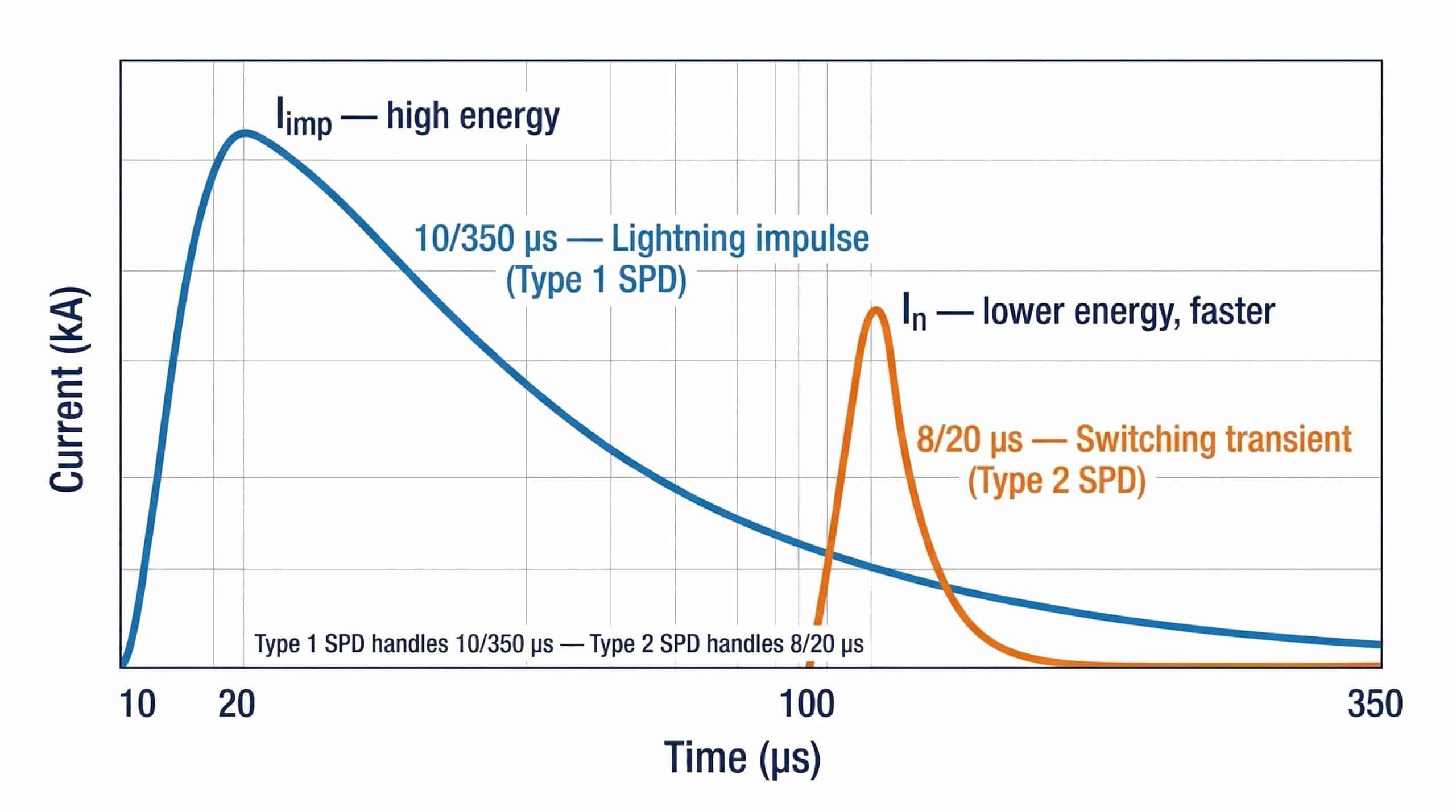
A direct strike injects current often exceeding 100 kA, requiring a Type 1 SPD tested with the high-energy 10/350 µs waveform. Far more common are indirect strikes — lightning hitting nearby ground or overhead lines, inducing transients via electromagnetic coupling. These indirect lightning-induced currents can reach several kiloamperes at the EVSE level, requiring SPDs rated ≥ 20 kA with a properly designed lightning protection system (LPS) and earthing.
3.2 Grid Switching Transients
Utilities continuously switch capacitor banks, transformer taps, and alternate energy feeds — each switching event generates a transient overvoltage that makes EV charger surge protection essential. While lower in energy than lightning, these occur daily or hourly, systematically degrading internal MOV components inside unprotected EVSE power supplies through cumulative stress — causing premature failure without a discrete event that would trigger insurance claims.
3.3 Internal Load Switching
When a 350 kW ultra-fast charger abruptly terminates a charging session (emergency stop, cable disconnect), the rapid change in current (di/dt) through inductive cables generates severe internal voltage spikes. These originate inside the charger cabinet — which is why AC-side protection alone is insufficient for DC fast chargers, and a DC fast charger surge protection strategy must include DC-side devices.
3.4 Electromagnetic Interference (EMI)
High-frequency noise from the EVSE's own switching inverters and rectifiers pollutes the local AC and DC bus. Advanced SPD designs incorporate EMI/RFI filtering to protect communication boards — Open Charge Point Protocol (OCPP) modules, CAN bus interfaces — from this high-frequency noise that can corrupt charging session data or trigger nuisance faults.
4. AC-Side vs DC-Side EV Charger Surge Protection: Key Differences
A critical misconception in EVSE design is that protecting the AC input is sufficient for complete EV charger surge protection — that's broadly true for Level 1/2 AC chargers, but Level 3 DC fast chargers need a strictly divided two-zone strategy.
4.1 AC-Side Protection
The AC side faces the raw utility grid. Its EV charger surge protection SPD must clamp incoming spikes before they reach the EVSE's internal PFC rectifier and AC-DC conversion stage. For outdoor commercial stations this typically requires a Type 1+2 combined SPD — providing both 10/350 µs direct-strike capability (Iimp) and tight 8/20 µs clamping for switching transients (In/Imax).
4.2 DC-Side Protection
The DC output side requires its own dedicated EV charger surge protection for three reasons:
- Transients are generated internally during AC-DC conversion and during sudden load interruptions (emergency stop during a 200 kW charge session)
- Long DC output cables to the vehicle can pick up induced surges
- DC arcs are significantly harder to extinguish than AC arcs — DC current does not naturally cross zero voltage — requiring specially designed MOV components with integrated thermal disconnects
DC SPDs (tested to IEC 61643-31) protect in three modes: (+) to PE, (−) to PE, and (+) to (−), with Up ≤ 2.5 kV per IEC 61851-23:2023.
4.3 AC vs DC SPD: Side-by-Side Comparison
| Feature | AC-Side SPD | DC-Side SPD |
|---|---|---|
| Location | Grid input, EVSE distribution board | DC output terminals to EV |
| Primary Threat | Lightning strikes, grid switching | Load switching, internal faults, cable surges |
| Applicable Standard | IEC 61643-11:2025 / UL 1449 | IEC 61643-31 / IEC 61643-41:2025 |
| Voltage Ratings (Uc) | 275 V, 320 V, 385 V, 420 V AC | 500 V, 800 V, 1000 V, 1500 V DC |
| Key Parameters | Iimp (Type 1), In / Imax (Type 2) | In, Imax (8/20 µs), DC arc quenching |
| TrilPeak Products | AC SPD range → | DC SPD range → |

5. SPD Selection Guide: Matching EV Charger Surge Protection to Charger Type
Correct Type 2 SPD EV charger specification requires mapping the EVSE topology, installation environment, and earthing system to IEC SPD classes — the table below does that mapping for six common charger configurations.
- Type 1 SPD — Direct lightning energy. 10/350 µs waveform. Rated by Iimp. Service entrances with overhead lines or external LPS.
- Type 2 SPD — Indirect lightning & switching transients. 8/20 µs waveform. Rated by In and Imax. Distribution boards, EVSE internal panels.
- Type 1+2 SPD — Combined. Industry standard for outdoor commercial DC fast charging hubs.
5.1 SPD Specification Matrix — 6 Charger Types
| Charger Type | SPD Type | Min. Iimp / In | Uc (AC) | DC-Side SPD | Standard |
|---|---|---|---|---|---|
| Level 2 AC, indoor (7–22 kW) | Type 2 | In ≥ 20 kA | 275 / 320 V | Not required | IEC 61643-11:2025 |
| Level 2 AC, outdoor | Type 1+2 | Iimp ≥ 7 kA | 275 / 320 V | Not required | IEC 61643-11:2025 |
| DC Fast (50–150 kW) | Type 1+2 AC + DC Type 2 | Iimp ≥ 12.5 kA | 275 V | In ≥ 20 kA @ DC bus Vdc | IEC 61643-11 + -31 |
| DC Ultra-Fast (150–350 kW) | Type 1+2 AC + DC Type 2 | Iimp ≥ 25 kA | 275 V | In ≥ 20 kA @ 1000–1500 Vdc | IEC 61643-11 + -31 |
| Solar-integrated EV hub | Type 1+2 AC + PV Type 2 | Iimp ≥ 12.5 kA | 275 V | In ≥ 20 kA @ 1000 Vdc | IEC 61643-11 + -31 |
| High-lightning-risk outdoor | Type 1 entrance + Type 2 sub-DB + signal SPDs | Iimp ≥ 25 kA | 275 V | Yes + data line SPDs | IEC 61643-11 + -31 |
TrilPeak product mapping for EV charging applications:
- Type 2 (In 20 kA, Imax 40 kA): TPK-40 series — DIN rail plug-in, TT/TNS/TNC earthing, remote signaling
- Type 1+2 (Iimp 7 kA, Imax 50 kA): TPK-7 series — plug-in, −40°C to +80°C
- Type 1+2 (Iimp 12.5 kA, Imax 60 kA): TPK-12.5 series — higher impulse for exposed sites
- Type 1+2 Monobloc (Iimp 15 kA, Imax 120 kA): TPK-I-15 series — service entrance protection
- DC PV/EVSE (up to 1500 Vdc, 3-pole Y): DC SPD series — IEC 61643-31 certified
6. 7 SPD Parameters Every Procurement RFQ Must Specify
Vague requirements like "must include surge protection" are unacceptable for commercial EV charger surge protection procurement — these 7 parameters must be explicitly stated to guarantee performance and enable valid supplier comparison.
1. Maximum Continuous Operating Voltage (Uc)
Uc must exceed the nominal system voltage. For 230/400 V AC: specify Uc ≥ 275 V or 320 V. For DC fast chargers: Uc must exceed the maximum DC bus architecture voltage (e.g., 1000 Vdc or 1500 Vdc for 800 V vehicle platforms).
2. Voltage Protection Level (Up)
The maximum let-through voltage during a surge. Must be lower than the impulse withstand voltage (Uw) of EVSE internal components. Specify Up ≤ 1.5 kV on the AC side. For DC-side SPDs per IEC 61851-23:2023: specify Up ≤ 2.5 kV.
3. Impulse Current (Iimp) — Type 1 SPDs
For outdoor commercial stations: minimum Iimp ≥ 12.5 kA per pole (10/350 µs). For high-exposure highway or rooftop locations: Iimp ≥ 25 kA per pole.
4. Nominal (In) and Maximum (Imax) Discharge Current — Type 2 SPDs
Specify In ≥ 20 kA (8/20 µs) for commercial installations. Specify Imax ≥ 40 kA. Residential-grade SPDs rated In = 5–10 kA are insufficient for commercial EVSE.
5. Earthing System Compatibility (TT / TN-S / TN-C)
SPD topology must match the local grid earthing system:
- TN-S / TN-C systems: 4-pole or 3+0 configurations (MOVs from all phases and neutral to PE)
- TT systems: 3+1 configuration (MOVs from phases to neutral; Gas Discharge Tube (GDT) between neutral and PE to prevent upstream RCD nuisance tripping)
6. Remote Signaling / Telemetry Dry Contact
Mandatory for B2B commercial operations. Specify dry-contact remote signaling (normally open/normally closed, NO/NC, changeover contact) so the SPD sends end-of-life alerts to the CPO's OCPP management platform. TrilPeak's TPK series includes an optional 3-pin NO/NC remote contact on all commercial models.
7. Third-Party Certification — No Self-Declared Compliance
Require:
- IEC 61643-11:2025 test report from an accredited national laboratory (not self-declared)
- CE marking with Declaration of Conformity
- CB scheme certificate for multi-market homologation
- TÜV Rheinland or VDE mark for highest-tier independent validation
7. EV Charger Surge Protection Installation: 7 Rules That Determine SPD Effectiveness
Even the best IEC-certified SPD is rendered ineffective by poor installation — these 7 rules are engineering non-negotiables for any EV charging station surge protection project.
The most violated installation principle: during a 10 kA surge (8/20 µs waveform), each 1 metre of connecting wire adds approximately 1,000 V of inductive drop (V = L × di/dt). If your SPD has Up = 1.5 kV but 1 m of connecting wire adds 1.0 kV, the EVSE sees 2.5 kV — destroying the electronics the SPD was installed to protect. Total lead length from SPD terminals to live/neutral busbars, plus SPD to PE busbar, must not exceed 0.5 metres combined. Use V-wiring (Kelvin connection) topology to minimise inductive loop area.
Rule #2 — Low-Impedance Grounding (< 10 Ω). An SPD diverts surge energy; it does not absorb it. The grounding system is the destination. Bond the EVSE chassis, SPD ground terminal, and structural canopy to a single equipotential earth reference, eliminating ground potential rise during a strike.
Rule #3 — Upstream Overcurrent Protection Coordination. Install a dedicated circuit breaker or fuse upstream of the SPD (unless the SPD has an integrated backup fuse). If the MOV fails short-circuit — a normal end-of-life failure mode — this breaker isolates the SPD safely without a station-wide outage. Consult the manufacturer's datasheet for required rating (typically 125A gG for standard plug-in Type 2 devices).
Rule #4 — Remote Monitoring Integration. Wire the SPD's dry-contact terminal to the charger's OCPP monitoring interface. This enables automatic end-of-life alerting, eliminating the risk of operating with a failed, unprotected SPD between scheduled site visits.
Rule #5 — Type 1 at Service Entrance, Type 2 at Panel. Never install a Type 2-only solution where a direct strike risk exists. Always cascade: Type 1 at the service entrance or MDB, Type 2 at the distribution board feeding the chargers.
Rule #6 — Data and Communication Line Protection. Protect all EVSE communication lines (Ethernet, RS-485, CAN bus) with signal-level SPDs rated per IEC 61643-21. A surge that bypasses power protection via the OCPP Ethernet port can still destroy control boards.
Rule #7 — Coordinate with the Earthing System (TT vs TN). In TT earthing systems, an incorrect 3+0 SPD topology will create a permanent leakage path between neutral and PE, tripping the upstream RCD immediately. Always match SPD topology to site earthing before installation.
8. Standards & Certifications Checklist for Procurement
Self-declared compliance is unacceptable for high-stakes EVSE infrastructure — the table below is what to actually verify for each certification, not just which logos appear on the datasheet. The Bourns application note on SPD selection for EV charging systems confirms that correct certification matching to installation requirements is the critical first step in vendor qualification.
| Certification | Market | What to Verify |
|---|---|---|
| IEC 61643-11:2025 | Global | Full third-party test report dated 2025. Verify accredited lab. Confirms Type, In, Imax, Iimp, Up parameters. |
| IEC 61643-31 / -41:2025 | Global | DC SPDs. Verify Uc covers full DC bus voltage (1000 Vdc or 1500 Vdc). Up ≤ 2.5 kV confirmed. |
| CE Marking | Europe / EEA | Must be accompanied by Declaration of Conformity (DoC) referencing IEC 61643-11:2025. |
| CB Scheme Certificate | Multi-market | International mutual acceptance. Accelerates homologation across multiple markets simultaneously. |
| TÜV Rheinland / VDE | Global (premium) | Highest-tier independent test lab marks. Guarantees rigorous IEC parameter validation. |
| UL 1449 5th Edition | North America | "UL Listed" Type 1 or 2 required — not merely "UL Recognized Component." Critical distinction for North American AHJs. |
| ISO 9001:2015 | Global — QMS | Verifies IQC, IPQC, OQC controls and full batch traceability across production. |
9. Conclusion
Specifying adequate EV charger surge protection is mandated by IEC 61851-23:2023, NEC 2023, and BS 7671:2018+A2:2022, and enforced by insurance and AHJ requirements in virtually every regulated market. As DC fast charger power levels scale toward 350 kW, the sensitivity of internal power semiconductors and the financial consequences of unprotected failure grow proportionally.
The correct approach is a two-stage architecture: a Type 1+2 SPD (IEC 61643-11:2025) on the AC input and a dedicated DC SPD (IEC 61643-31) rated Up ≤ 2.5 kV on the DC output side. Correct installation — particularly the 0.5-meter lead length rule and low-impedance equipotential grounding — is as critical as the device specification itself.
For OEM EV charger manufacturers seeking a vertically integrated, IEC and TÜV certified SPD supplier with flexible MOQ and rapid prototype capability, explore TrilPeak's Type 1+2 SPD range and DC SPD series.
10. Frequently Asked Questions
10.1 Does my EV charger legally require surge protection?
Yes, in most regulated markets — and the underlying reason is that EV chargers combine outdoor exposure, high-power semiconductors with narrow voltage tolerance, and connection to a vehicle's onboard electronics, all in one installation. In the UK, BS 7671:2018+A2:2022 requires SPDs for virtually all new commercial EV charging installations — the installation owner must formally opt out and document the accepted risk. In the US, NEC 2023 Section 230.67 mandates SPDs for dwelling-unit services, and commercial sites face AHJ and insurance requirements that effectively enforce SPD compliance. IEC 61851-23:2023 functionally mandates DC-side EV charger surge protection for any DC charging station seeking CE marking.
10.2 What is the difference between Type 1 and Type 2 SPD for EV chargers?
Type 1 SPDs handle direct lightning strike energy, tested with a high-energy 10/350 µs waveform and rated by Impulse Current (Iimp). They are installed at the primary service entrance. Type 2 SPDs handle indirect lightning and switching transients, tested with an 8/20 µs waveform and rated by Nominal Discharge Current (In), providing tighter voltage clamping closer to sensitive EVSE electronics. Most outdoor commercial DC chargers require a combined Type 1+2 SPD at the AC input and a dedicated DC SPD (IEC 61643-31) at the output.
10.3 Can I use a residential surge protector for a commercial EV charger?
No. Residential SPDs are designed for single-phase 120/240 V with In = 5–10 kA. Commercial DC fast chargers operate on three-phase 400 V or 480 V and require In ≥ 20 kA on the AC side, plus dedicated DC-side protection rated to 1000–1500 Vdc. Residential SPDs also lack earthing system flexibility (TT/TN-S/TN-C), remote telemetry interfaces, and the IEC 61643-11:2025 certification required for commercial EVSE documentation and insurance compliance.
10.4 What happens if a DC fast charger is struck by lightning without SPD?
The induced transient will instantly destroy the PFC rectifiers, IGBT/SiC MOSFET inverter stages, and control boards. The surge propagates through the DC output cable into the connected vehicle, potentially destroying the vehicle's BMS and onboard charger. Complete charger cabinet replacement is typically required. With a vehicle connected at the time, the Charge Point Operator faces serious product liability exposure — making surge protection for EV chargers a risk management imperative, not just an engineering preference.
10.5 How do I specify a surge protection device for an EV charger RFQ?
A complete RFQ specification must state: SPD Type (1, 2, or 1+2), Uc for AC and DC lines, Iimp (for Type 1), In and Imax (for Type 2), maximum allowable Up, earthing system compatibility (TT / TN-S / TN-C), remote monitoring dry-contact requirement, and third-party certification requirements (IEC 61643-11:2025, CE, CB, TÜV or VDE). Specifying only "IEC-certified surge protector" creates ambiguity that suppliers will exploit with minimum-spec products.
10.6 What is the correct installation position for an EV charger SPD?
On the AC side, install the SPD in parallel as close as possible to the EVSE distribution board incoming terminals. On the DC side, install in parallel at the DC output terminals. The critical rule: total connecting wire from SPD terminals to live/neutral/PE busbars must not exceed 0.5 meters combined, or inductive voltage drop will negate the SPD's clamping performance regardless of its rated Up — a common and costly installation error.
10.7 Do DC fast chargers need DC-side SPD in addition to AC-side protection?
Yes, always. AC-side SPDs protect against grid anomalies and atmospheric surges but cannot protect against transients generated internally by the charger's load switching or DC-DC converter faults. IEC 61851-23:2023 formally requires DC-output protection with Up ≤ 2.5 kV. Specify an IEC 61643-31 certified DC SPD in (+)-PE, (−)-PE, and (+)-(−) protection modes at the output terminals of every DC fast charger installation.
10.8 How often should EV charger surge protectors be replaced or inspected?
MOV-based SPDs degrade incrementally with each absorbed surge — there is no fixed calendar replacement interval. Schedule visual inspection during annual EVSE maintenance. Critically, wire the SPD's dry-contact remote signal to your CPO management platform for automatic end-of-life alerts. Pluggable cartridge designs such as TrilPeak's TPK series allow on-site replacement in minutes without disrupting the distribution board. Never operate EVSE whose SPD status indicator shows a fault condition.
Related Resources & Standards
Need IEC-Certified SPDs for Your EV Charger Project?
TrilPeak manufactures IEC 61643-11:2025 and IEC 61643-31 certified SPDs for EV charger AC and DC protection — direct from manufacturer with full third-party test documentation for OEM integration and B2B procurement.